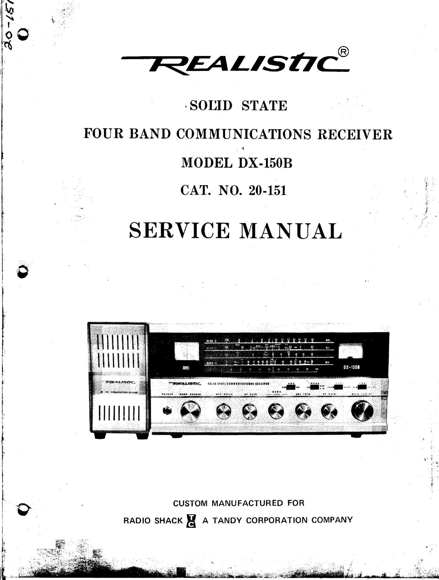
Realistic dx 150 b service manual

This is the 48 pages manual for realistic dx 150 b service manual.
Read or download the pdf for free. If you want to contribute, please mail your pdfs to info@audioservicemanuals.com.

Page: 1 / 48
left right
realistic dx 150 b service manual

Extracted text from realistic dx 150 b service manual (Ocr-read)


Page 2

d
.

. I
CONTENTS I

SPECIFICATIONS ..........................................................................................................................................
GENERAL ALIGNMENT INSTRUCTIONS ..... K ............................................................................ , ............
FIGURE 1. FRONT VIEW OF Dx-IBOB ..................... . .......................................................................
FIGURE 2. TOP VIEW OF DX-1SOB CHASSIS ....................... .. .................... .. ...............................
FIGURE 3. BOTTOM VIEW OF DX-1SOB .............................................................................. . ........
INSTRUCTIONS FOR REMOVAL OF CHASSIS AND DIAL CORD ASSEMBLY .............
FIGURE 4. CHASSIS DISASSEMBLY ................................................................................................
FIGURE 5. I

AND BAND SELECTOR..........; ........................................................................................
FIGURE 6. KNOB & SHAFT ASSEMBLY FOR BFO PITCH, AF GAIN, ANT TRIM

AND RF GAIN ..................................................................................................................
FIGURE 7. PHONE JACK ASSEMBLY .............................................................................................
FIGURE 8. MAIN TUNING DIAL STRINGING ASSEMBLY ....................................... . ....... . ......
FIGURE 9. BAND SPREAD DIAL STRINGING ASSEMBLY ......................................................
FIGURE 10. PRINTED CIRCUIT BOARD PARTS LOCATION (TOP VIEW) ...........................
FIGURE 11. PRINTED CIRCUIT BOARD PARTS LOCATION (FOIL SIDE) ...........................
FIGURE 12. PRINTED CIRCUIT BOARD WIRING DIAGRAM ...................................................
FIGURE 13. SCHEMATIC DIAGRAM ...................................................................................................
PARTS LIST ............................................. , ......................................................................................................

Notice:

This Service Manual is for products manufactured from Oct. 2, 1972.
In replacing parts recognized by UL or CSA, use only recognized ones which
have the same value.

Page
1

b-bCAJOOMd

U1

dOCOmxlCDCDU'IUI

dd