Rane MA 6 Multi Channel Amp Schematics

This is the 5 pages manual for rane MA 6 Multi Channel Amp Schematics.
Read or download the pdf for free. If you want to contribute, please mail your pdfs to info@audioservicemanuals.com.

Page: 1 / 5
left right
rane MA 6 Multi Channel Amp Schematics

Extracted text from rane MA 6 Multi Channel Amp Schematics (Ocr-read)


Page 1

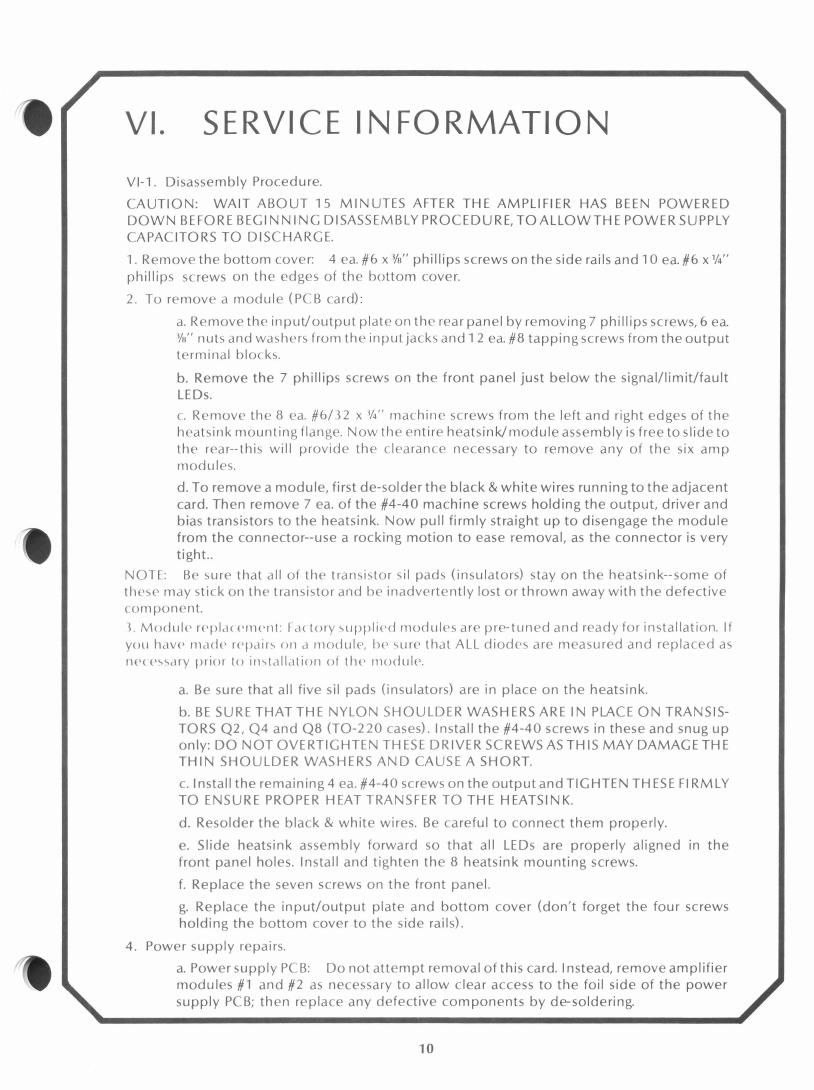
b. Transformer removal: The transformer is held in place by four l/4" bolts into separate nuts on the right side and a retaining nut plate on the left side. To remove the two right-side bolts, it is necessary to remove the heatsink assembly to gain access to the two nuts. Remove the 8 heatsink mounting screws, 7 front panel screws and 7 input/output plate screws: now you may slide the heatsinkassembly to the rearand lift it up, out and to the left to gain access to the transformer nuts. The two left-side transformer bolts can simply be loosened until the nut plate falls off. Pull all transformer spade plugs from the power PCB and lift the transformer out of the chassis (brace yourself). To replace the transformer, reverse the above procedure; it is necessary to hold the nut plate in place with your fingers to install the two left-side transformer bolts. Reconnect all transformer spade plugs as shown on the power board assembly diagram. VI-2. Schematics and assembly diagrams.

Page 2