Quad ESL 63 Service Manual

This is the 25 pages manual for Quad ESL 63 Service Manual.
Read or download the pdf for free. If you want to contribute, please mail your pdfs to info@audioservicemanuals.com.

Page: 1 / 25
left right
Quad ESL 63 Service Manual

Extracted text from Quad ESL 63 Service Manual (Ocr-read)


Page 1

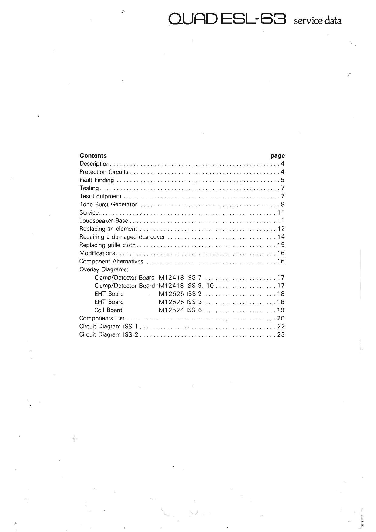
QUQD ESLBB service data

Contents page
Description .................................................. 4
Protection Circuits ............................................ 4
Fault Finding ................................................ 5
Testing ..................................................... 7
Test Equipment .............................................. 7
Tone Burst Generator .......................................... 8
Service .................................................... 11
Loudspeaker Base ........................................... 1 1
Replacing an element . . _ ..................................... 12
Repairing a damaged dustcover ................................ 14
Replacing grille cloth ......................................... 15
Modifications ............................................... 1 6
Component Alternatives ...................................... 16
Overlay Diagrams:
Clamp/Detector Board M12418 ISS 7 ..................... 17
Clamp/Detector Board M12418 ISS 9, 1O .................. 17
EHT Board M12525 ISS 2 ..................... 18
EHT Board M12525 ISS 3 ..................... 18
Coil Board M12524 ISS 6 ..................... 19
Components List ............................................ 20
Circuit Diagram ISS 1 ........................................ 22

Circuit Diagram lSS 2 ........................................ 23

Page 2

4

u

QURD ESL 83 service data
description

The Quad ESL-63 is a full range electrostatic loudspeaker doublet. It consists of a very light electrically polarised
diaphragm suspended between two sets of concentric annular electrodes. Signal is fed to the electrodes via
sequential delay lines and the motion of the diaphragm produces a sound pressure pattern which is an exact replica
of that from an ideal source placed some 30- cms behind the plane of the diaphragm.

protection circuits

The audio input is fed to the audio transformers via a clamp circuit. Input signals in excess of 40\7 are then clamped
such that signal ted to the loudspeaker elements is kept within safe limits. If however. the clamp circuit runs
continuously it can overheat and become damaged.

Sparks oceurring within the loudspeaker are detected by an antenna situated in the loudspeaker base. The detector
circuit will then cause temporary shutdown of the loudspeaker by short circuiting the input for a pre-determined
period of time. The detector circuit will also operate it input signal is applied in the absence of AC supply volts.