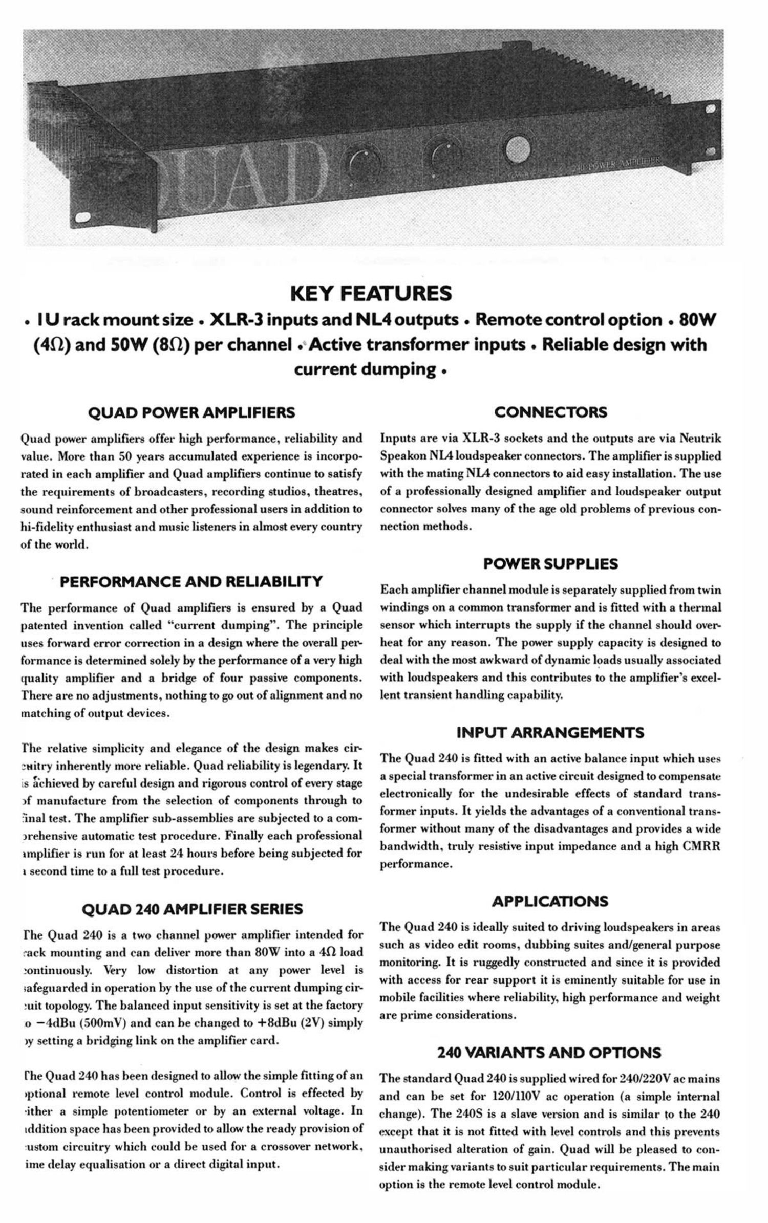
Quad 240 Brochure

This is the 2 pages manual for Quad 240 Brochure.
Read or download the pdf for free. If you want to contribute, please mail your pdfs to info@audioservicemanuals.com.

Page: 1 / 2
left right
Quad 240 Brochure

Extracted text from Quad 240 Brochure (Ocr-read)


Page 1

KEY FEATURES

. IU rack mount size . XLR-3 inputs and NL4 outputs . Remote control option . 80W
(40) and 50W (80) per channel .~Active transformer inputs . Reliable design with
current dumping .

QUAD POWER AMPLIFIERS

Quad power amplifiers offer high performance, reliability and
value. More than 50 years accumulated experience is incorpo-
rated in each amplifier and Quad amplifiers continue to satisfy
the requirements of broadcasters, recording studios. theatres.
sound reinforcement and other professional users in addition to
hi-fidelity enthusiast and music listeners in almost every country
of the world.

PERFORMANCE AND RELIABILITY

The performance of Quad amplifiers is ensured by a Quad
patented invention called current dumping. The principle
uses forward error correction in a design where the overall per-
formance is determined solely by the performance of a very high
quality amplifier and a bridge of four passive components.
There are no adjustments, nothing to go out of alignment and no
matching of output devices.

The relative simplicity and elegance of the design makes cir-
2uitry inherently more reliable. Quad reliability is legendary. It
.s achieved by careful design and rigorous control of every stage
)f manufacture from the selection of components through to
:inal test. The amplifier sub-assemblies are subjected to a com-
)rehensive automatic test procedure. Finally each professional
implifier is run for at least 24 hours before being subjected for
I second time to a full test procedure.

QUAD 240 AMPLIFIER SERIES

The Quad 240 is a two channel power amplifier intended for
tack mounting and can deliver more than 80W into a 40 load
:ontinuously. Very low distortion at any power level is
safeguarded in operation by the use of the current dumping cir-
:uit topology. The balanced input sensitivity is set at the factory
o -4dBu (SOOmV) and can be changed to +8dBu (2V) simply
)y setting a bridging link on the amplifier card.

The Quad 240 has been designed to allow the simple fitting of an
rptional remote level control module. Control is effected by
ither a simple potentiometer or by an external voltage. In
uddition space has been provided to allow the ready provision of
-ustom circuitry which could be used for a crossover network.
ime delay equalisation or a direct digital input.

CONNECTORS

Inputs are via XLR-3 sockets and the outputs are via Neutrik
Speakon N [A loudspeaker connectors. The amplifier is supplied
with the mating NIA connectors to aid easy installation. The use
of a professionally designed amplifier and loudspeaker output
connector solves many of the age old problems of previous con-
nection methods.

POWER SUPPLIES

Each amplifier channel module is separately supplied from twin
windings on a common transformer and is fitted with a thermal
sensor which interrupts the supply if the channel should over-
heat for any reason. The power supply capacity is designed to
deal with the most awkward of dynamic loads usually associated
with loudspeakers and this contributes to the amplifiers excel-
lent transient handling capability.

INPUT ARRANGEMENTS

The Quad 240 is fitted with an active balance input which uses
a special transformer in an active circuit designed to compensate
electronically for the undesirable effects of standard trans-
former inputs. lt yields the advantages of a conventional trans-
former without many of the disadvantages and provides a wide
bandwidth. truly resistive input impedance and a high CMRR
performance.

APPLICATIONS

The Quad 240 is ideally suited to driving loudspeakers in areas
such as video edit rooms, dubbing suites and/general purpose
monitoring. It is ruggedly constructed and since it is provided
with access for rear support it is eminently suitable for use in
mobile facilities where reliability, high performance and weight
are prime considerations.

240 VARIANTS AND OPTIONS

The standard Quad 240 is supplied wired for 240/220V ac mains
and can be set for 120/110V ac operation (a simple internal
change). The 2405 is a slave version and is similar to the 240
except that it is not fitted with level controls and this prevents
unauthorised alteration of gain. Quad will be pleased to con-
sider making variants to suit particular requirements. The main
option is the remote level control module.

Page 2

Performance specification

power output 80W
50W
power output response lOHz- 30kHz
frequency response 20Hz-20kHz
group delay* <6us
group delay error* < | .Sus
distortion <00 3%
<0.0 l %
<0. I %
dynamic range (hum + noise) > l08dB
input sensitivity
selectable internally 2V
or 500mV
remote control option
control signal 0V to 5V
control range >80dB
interface connector 9 way D type
input impedence > lOkQ
common mode rejection >60dB
common mode range 250V
input connector XLR- 3
output connector NL4
output impedance 0.0 30
output voltage offset 7mV
channel separation >80dB
load stability any load
power requirements ZSOVA
working mains voltage 250/220Vac
I 25/ I IOVac
indicators LED's
protection
thermal 85°C
peak current I 0.SA
dc offset
dc supply fuse 6. 3A
mains fault TZA
T4A
operating temperature 0°C to 45°C
weight 5.4kg
dimensions overall 483 x 45 x 350mm

*Group delay is a measure of the transit delay of signals
passing through the amplifier. Group delay error is a
measure of the delay experienced by the frequency
components of a complex signal passing through the
amplifier.

40 load. per channel. 240Vac supply
80 load. per channel. 240Vac supply
<0. l % THD+N. T amb 20°C

- 3dB ref l kHz 50W 80

-O.SdB ref l kHz

at l kHz. amplifier output is non-inverting
up to 20kHz ref l kHz

THD+-N. 40H: any level up to 50W 80
THD+ N. lkHz any level up to 50W 80
THD+ N. 20kHz any level up to 50W 80

A wtd ref full signal output. ( I 5.7kHz bandwidth)

for full output
(+8dBu) equivalent to ppm 6. 22dB gain
(-4dBu) 34dB gain

plug-in module
or IOkQ potentiometer

mounted on rear panel

balanced. nominal. resistive
20Hz to l0kHz
SOHz

chassis socket wired to lEC
pin l = chassis. pin 2 = hot, pin 3 = cold

wired to the low outpUt impedance convention

l+ = signal. I - = return. 2+ and 2- not conneCted
at l kHz nominal. in series with l.5].tH
typical

l kHz. inputs terminated
unconditional
with bath channels delivering 80W into 40

note that lower supplies will reduce output power
internal transformer tapping change

indicates dc supplies for each channel

internal heatsink temperature

peak output current limit internal protection
power supply 0V centering circuit

internal dc power supply fuse

240Vac mains fuse

l 20Vac mains fuse

high ambient temperatures require full ventilation
without packing
width (l9 inch rack). height ( I U). depth

Power
l20 (W) l t

I

l
l
l, ...l instantaneous
' ' ' "N l
l

90 .__1__,_,____
/l

so / Jr l .
/ l g ; continuous
: l i
30 l , I : l
. | i
load resistance ($2)
i 2 3 4 s 6 7 8 9 "

\

~

~
-
s

2/90