Pyle plvwcrk 5 owners manual

This is the 2 pages manual for pyle plvwcrk 5 owners manual.
Read or download the pdf for free. If you want to contribute, please mail your pdfs to info@audioservicemanuals.com.

Page: 1 / 2
left right
pyle plvwcrk 5 owners manual

Extracted text from pyle plvwcrk 5 owners manual (Ocr-read)


Page 1

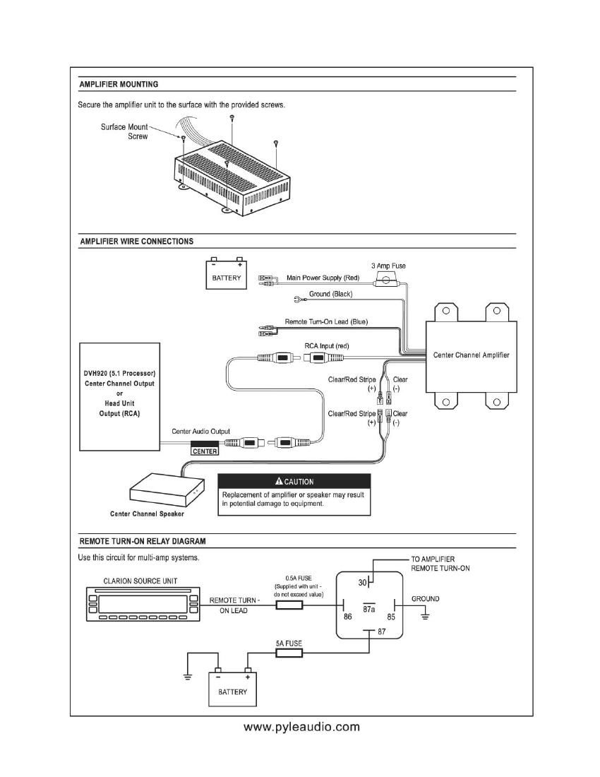
AMPLIFIER MOUNTING

Secure the amplifier unit to the surlace with the provided screws.

AMPLIFIER WIRE CONNECTIONS

'3

e3

BATTERY

Main Power Supply (Red)

3 Amp Fuse

Ground (Black)


nvmzo [5.1 Frontier)
Center Channel Output
or

RCA Input (red)

Clear/Red Stripe

Rennie Tum-On Lead (Blue)


Center Channel Amplifier

CLARION SOURCE UNIT 05A FUSE

(Supplied with unit -
do nut exceed value)

C]

REMOTE TURN -
ON LEAD

CI
8

DDDDDDDDD

5A FUSE


E
85

'87

[]

l l

BATTERV

Head Unit 0 0
Output (RCA) Clear/Red Stripe Clear
(*l (-l
Center Audio Output
- I
-
A CAUTION
Replacement of amplifier or speaker may result
in potential damage to equipment
Center Chlnnel Speaker

REMOTE TURN-0N RELAY DIAGRAM
Use this circuit for multi-amp systems. _ To AMPLIFIER

REMOTE TURN-ON

GROUND

www.pyleaudio.com

Page 2

P LVWC RK5 1/2 DIN Center Channel Speaker and Amplifier

Installation I Wire Connection Guide

FEATURES

- High power 50W maximum poweramplifier.

Five (5) - 3/4' front mounted full range drivers for mid and high frequencies.

Two (2) - 1' rear mounted drivers for accurate mid-bass response

This design delivers clear and precise sound to your 5.1 surround sound system.
- Dynamic audio sound is achieved from speakers 1 or less in diameter by utilizing strong neodymium boron magnets.
- Included with the center channel speaker are mounting brackets and hardware for ease of installation.
0 The compact design of the central channel speaker allows installation into virtually any 1/2 DIN opening.

ACCESSORIES

ITE M QTY

Surface mount screws
Bracket mount screws .
Brackets ,.


Owner's Manua

Warranty Statement

SPECIFICATIONS

Amplifier Speaker Box

Continuous Power Output 25W (1 kHz @ into 4 Ohm at 1% THD) Five (5) - 3/4" Full Range Speakers
Peak Power Output 50W Two (2) - 1' Low Frequency Speakers
Distortion 0.1% at 1.0W 1kHz Peak Power Input ....... 50W
SIN 70GB (0dB=1kHz 1W4 Ohm) Continuous Powerlnput. ,25W
Input Sensitivity 200mV to 4V Dimensions , , 1"H x 6-3/4'1 x 6-1/2"L
Frequency Response 450Hz to 29kHz Weight .0.5Ib
Power Supply Voltage 10.8V to 15.6V

Current Consumption 3A

Dimensions 1-3/4'H x 3-3/8"W x 5-3/4'L

Weight 1lb

CENTER CHANNEL SPEAKER INSTALLATION

1. Determine the desired location for center channel speaker
and amplifier insuring there is an adequate space for the
speaker enclosure and ventilation tor the amplifier.

2. Install center channeI speaker with provided brackets and
screws.

3. Mount amplifier using provided screws

4. Connect the speaker wire from the amplifier to center channel
speaker. (Clear/Red stripe wire is positive).

5. Connect a RCAlrom your head unit or processor's center channel
output to the amplifiers input.

6. Connect the ground wire from the amplifier to good.
clean chassis spot.

7. Run 10 gauge wire from the battery to power input in the amplifier.
(Fuse appropriately at the battery),

8. Connect the remote power turn-on circuit from your head unit to
the blue wire on the amplifier, (May require additional relay),

9. Adjust the input sensitivity on the amplifier to avoid clipping or
distortion.

AWAHNING

Installation of the center channel speaker or amplifier on or near
vehicle's air bag can result in serious Injury or damage to the unit,

B raéet
Screw

Clear (-)

Clear/Red Stripe (+)


Bracket

Installation Surface