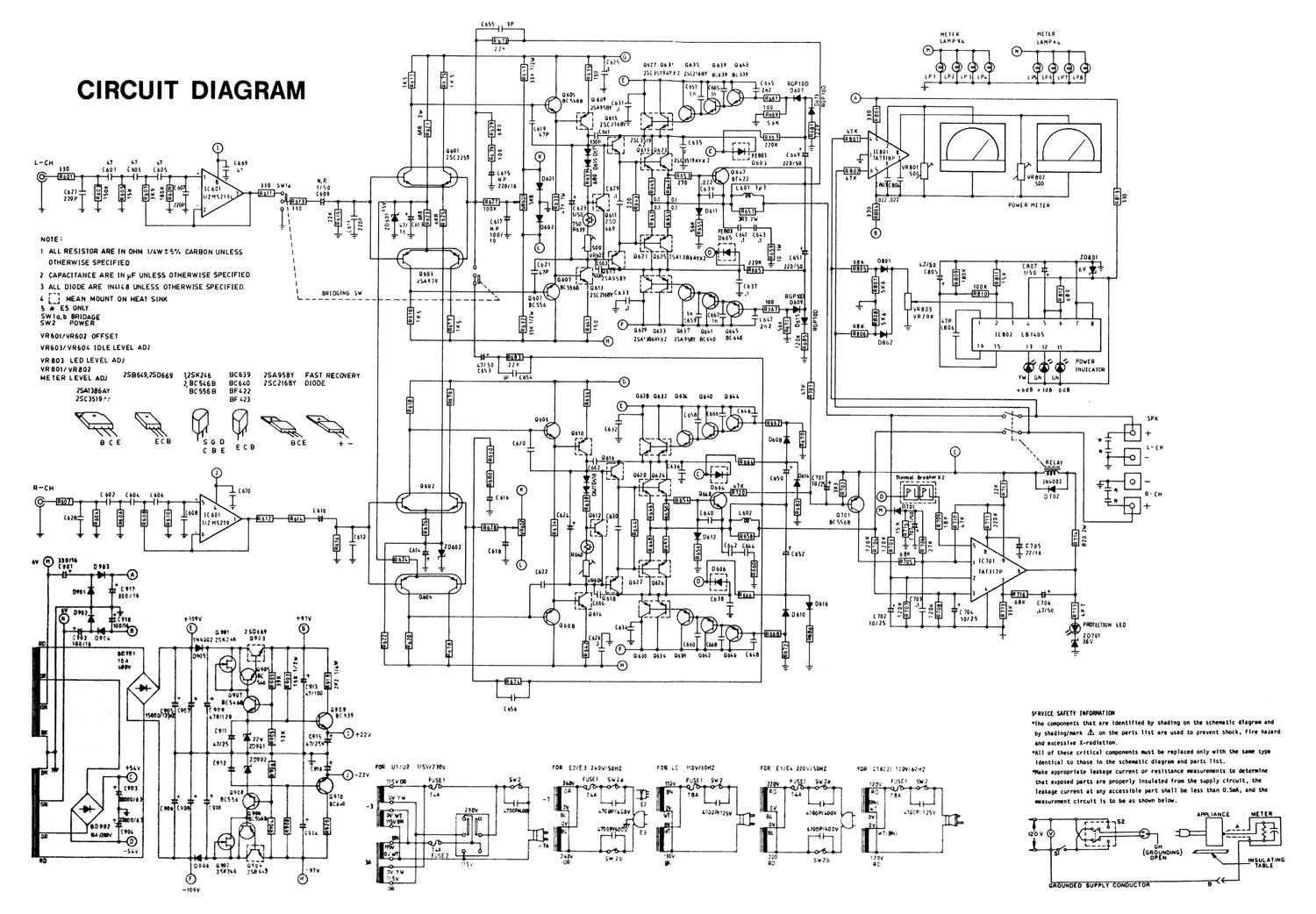
Proton d 1200 schematic alt

This is the 1 pages manual for proton d 1200 schematic alt.
Read or download the pdf for free. If you want to contribute, please mail your pdfs to info@audioservicemanuals.com.

Page: 1 / 1
left
proton d 1200 schematic alt

Extracted text from proton d 1200 schematic alt (Ocr-read)


Page 1

I mm: HEIlR
m ' UH!- LAHPAI.
22k
4 f 4r , I;
g I?" can 063' am am 0663
.n': 2 E: 3 '55 E 250519;.sz zmmaY 3-4939 3L5 LPi LP2 LP) LPI. l LPb LP? LPG
O O M I
Cl RCU I I D I AG RAM 3: " «s Lat? 3:320 g £-
0605 . In in ,
Y b I 4.. sum: 060 m,__ a... 6' . 3 C):
3 ____ 29953? .1 -fi 100 T
N .. l . nus . j 1-9:. V
I; o 'I' l 25( max:- I i =- 55K . _
g: '3 3, t" " (on " "" nx
I. .
I" l ESP-i II I
o e '23" I 25ch 9 2 35 r--1 220x fl
0601 F O ) L J 0612 0£_3 '0' so;
25(2259 3 S F 5 '- us 35,, 2 L__J°°3 9? Imiap
L-CH 4.1 4.7 t1 8 , " coo; 229/50 R -
(so; (005 L... .. =- 7 7- v am
01 "° 6 3 A vnaoz
0° 3 3 5 o no .022 5" +. 500
x o {6?9L 0 (039 L601 3p!
" 3 t" l a o e .6 3°
'- n ,. - m | db O V: 0 0i 2 z:
o: [623 2° 0 01 pOWERNETER
4 ' 4 I ' 06" 6 7
50 06" 5 . R3 2W
, 750 50 x
60' m9 559 3 o |--l
r- -- °= mos (th (m
500 ' =-
l ALL RESISIOR ARE IN OHM m 2 °/ AR - L- --
w 5 ' C BON UNLESS V960 F l mm 0625 Isuaaouxz
OIHERWISE SPECIFIED. cw _ (3 J
1.79 i- '
2 CAPACITANCE ARE lN pF UNLESS OIHERWISE SPECIFIED 1 am J'Wfimsav . .. -., a;
3 ALL DIODE ARE mace UNLESS OlHERWiSE SPECIFIED. usua- om ' v
r-1 amoomo 5»: 23mm): - -I
a L} MEAN MOUNT ON HEAl SINK \- - +-- - 0607 -i
s a» £5 ONLY 55° 4; J , o ]
SWIM: BRIDAGE ,_ " (66 s:
swz POWER 3 3 ® 5 "I g 2 a
" " 0629 am 0637 can nus
ll.
VR60VVR602 OFFSEI J @ zsa'aemxz zsnsav acuo aim ltaoz L8 05
VR603/VR604 IDLE LEVEL ADJ V: I3 I2 ll
VR803 LED LEVEL ADJ I I 1 (I POW!
VR BOIIVROOZ INOILAIOR
MElER LEVEL ADJ 25869250669 lISKZis BC639 2SA958Y FASI RECOJERY w on 6
zacswa aceco zsczIsav DIODE © 3 _ a
ZSAIJBGAY BCSSSB 8H2? _ 3 2 +06 was one
2505,, BF 23 9 5 am am 063 am am L-I
f O : SPK
x .I t o .L fE +
S 5 D BCE + _. -\ I
C B E E c a \\\ * IFS- LCH
\fw , -
(7m. + lhemel Dachau moo: - o
10/ 1+2 :r' .E E; '51.. I
° 0 I m 0702 I I ' (H
3 L " +
(m 070 0
II. : M59015 5.
UN
2 z 1?.
a 5. nos ° °°
" mu
. 0
no '
t 2 0616 m' :E .1 35 + i" 68K (773:0 h v~
u m .4 F. I.
How "w {. °° -- _ . $ om L702 1: . 1: (ms t; m g ,,
x J l 10/25 «-
o 0603 to) \1 anmon LEO
cm zsous G) I I 6 m 2070:
mm: zsxm 990! cue-l J 3 =
- 1- "" 364
E .1 . mo (as a»
.- 3 am am am am am (a ,. r
. ® : "2'
W
II
i name PM, so SRVICE samv Iuromnon
* 'lhe components that are identified by shading on the schematic diagra- and
(9" S o 22" by shading/mark A on the parts list are used to prevent shock. fire hazard
ans 5 and excessive x-radiation.
'All of these critical components last be replaced only with the sane type
(Oi! Identical to those in the schenatic diagram and parts list.
I.H II I w . , ,
o -2" rain U J2 In" r" ENE) hows: F LC WWW": NR (u OWN FOR 1?! W'wfl 'iiake appropriate leakage current or resistance IIeaSurenentsto detemine
1? Hi 95 5'3 2m 5 5 "J fl 5 ,2. USE! SW that exposed parts are prOperly insulated from the supply circuit. the
I -' :3 g i i , leakage current at any accessible part shall be 1035 than 05d. 006 "0
an» -3 -7 [2 I H l ? measurement circuit is to be as shown below.
WWW" ' momzsv m * mowwov JGGPIIzsv annucc acne
s is tmmwov
-7 l I ( 8H )
on UNOING
. -- V sun msuunuc
moo am mot 3a , 0 " 3' 5 TABLE
Isuzu new ~97v
o 0 on uno 0 open con DC on 649

-l09¥ (I?