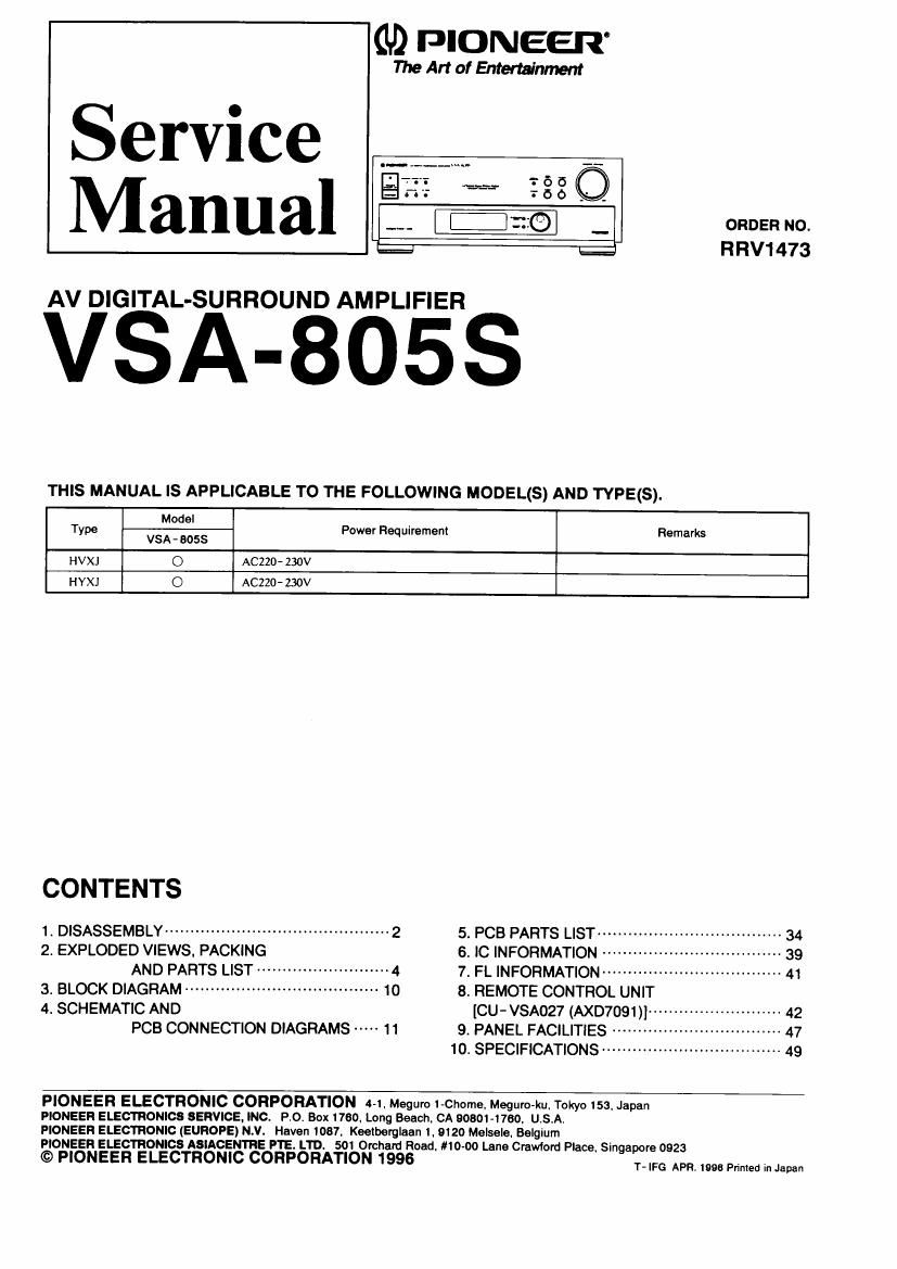
Pioneer vsa 805 service manual

This is the 34 pages manual for pioneer vsa 805 service manual.
Read or download the pdf for free. If you want to contribute, please mail your pdfs to info@audioservicemanuals.com.

Page: 1 / 34
left right
pioneer vsa 805 service manual

Extracted text from pioneer vsa 805 service manual (Ocr-read)


Page 1

(U) PIONEER

The Art of Entertainmem

Service
Manual no -_

' I= RRV1473

AV DIGITAL-SURROUND AMPLIFIER

VSA-BOSS

THIS MANUAL IS APPLICABLE TO THE FOLLOWING MODEL(S) AND TYPE(S).

Model

T Power R uirement Remarks
ype VSA- 805$ eq

HVXJ O ACZZD- 230v
HYXJ O ACZZO- 230v


CONTENTS

1. DISASSEMBLY ............................................ 2 5' PCB PARTS LIST ..................... . 34

2. EXPLODED VIEWS. PACKING 6. IC INFORMATION " 39
AND PARTS LIST .......................... 4 7. FL INFORMATION ................................... 41

3. BLOCK DIAGRAM ------------------------------------ 10 8. REMOTE CONTROL UNIT

4. SCHEMATIC AND [CU-VSA027 (AXD7091)] -------------------- 42
PCB CONNECTION DIAGRAMS """ 11 9. PANEL FACILITIES """"

10 SPECIFICATIONS ................................... 49

PIONEER ELECTRONIC CORPORATION 4-l. Meguro I»Chome. Meguro-ku, Tokyo 153. Japan

PIONEER ELECTRONICS SERVICE, INC. PO. Box 1160. Long Beach. CA 905014760, U.S.A,

PIONEER ELECTRONIC (EUROPE) N.V. Haven 1087. Keereyglaan 1.9120 Melsale. Belgium

PIONEER ELECTRONICS ASIACENTRE PTE. LTD. 501 Orchavd Road. #1000 Lane Crawford Place, Singapore 0923

© PIONEER ELECTRONIC CORPORATION 1996 we m ,9 PM, Mm"

Page 2

VSA - 8055

1. DISASSEMBLY

- CAUTION l

taken off.

more than SW/lo Q.

more than 5W/10 Q.

You will get an electrlc shock If you touch the Radiator (Heat-slnk) when the AC power cord is
connected to the power source. Also, the Electrolytlc Capacltor contains a charge even when
the Ac power cord ls unplugged. so the charge must be removed when the bonnet has been

@Connect the Radiator (top side) and either the Chassis or the Rear panel for 2 to 3 seconds with a Resistor of

®Connect the +B lead on the 12 and either the Chassis or the Rear panel for 2 to 3 seconds with a Resistor of

1.1 PS 8i FUNC ASSY

. Remove the Bonnet case.

. Remove the two screws® ,

. Remove the screw®.

.Remove the four screws 6) holding the PS & FUNC

assy.

5. Remove the Round knob L and remove the screw @
between the volume and the front panel.

6. Remove the Vol. assy from the PS & FUNC assy.

7. Remove the rear panel, and power block from the
chassis at the same time, according to the Fig. l.

awry--

VOL, Assy

i\ Korew®

Screw (D

Screw @

Front Panel

Screw® PS 8. FUNC Assy
l\ \

\O \

W10.

fi=

Power Block

\

Ll
Rear Panel Screw®

Chassis

Fig.1