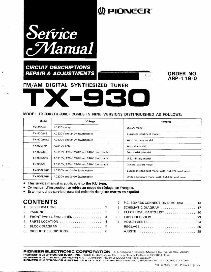
Pioneer tx 930 service manual

This is the 29 pages manual for pioneer tx 930 service manual.
Read or download the pdf for free. If you want to contribute, please mail your pdfs to info@audioservicemanuals.com.

Page: 1 / 29
left right
pioneer tx 930 service manual

Extracted text from pioneer tx 930 service manual (Ocr-read)


Page 1

1. SPEC|FICATIONS FM Tuner Section Usable Sensitivity 10.8dBf (0.9bpV) 50dB Ouieting Sensitivity Mono; 15.8dBf 11.7ttYl Stereo;38dBf (229V) Signal-to-Noise Ratio Mono; 78dB (at 85dBf) Stereo;75dB (at 85dBf) Distortion (at 65dBf) Mono. ....1kH2;0.0fflo Stereo ....1kH2:O.1So/o CaptureRatio. ....1.0d8 AlternateChannelSdtactivity . ... 400kHz;SOdB stereo separation i;;il;lllff;i3:3 Frequency Response . . . . 2OHz to l5kHz 1?.30A SpuriousResponseRatio. ...70d8 lmage Response Ratio . 40dB lF Response Ratio . . .80d8 AM Suppression Ratio . SOdB Muting Threshold . . 19.2dBf (SpV) Antenna Input . 3(X)ohms balanced, 7Sohms unbalanced AM Tuner Section Sensitivity (lHF, external antenna) 30pV Selectivity ....2tu8 Signal-to-NoiseRatio ..S0dB lmage Response Ratio . 40dB lF Response Ratio . . .60dB .Antenna ....Loopantenna Audio Section FM (100% MODI . 6S0mV/2.2kQ AM (307o MOD) . l90mV/2.2k0 Miscellaneous Power Requirements AC120V,60Hz Power Consumption l Twatts Dimensions 420(W) x 69(H)x 219(D)mm 1 6-9/19(w) x 2.11 /16(Hl x 8-5/8(D)in Weight (without package) . . 2.9kg (6tb 6oz) Furnished Parts FMT-typeAntenna ....,l AM Loop Antenna l AntennaCatcher ......1 ConnectionCordwithPinPlugs ...... l Operatinglnstructions ........1 NOTE: Specifications and design subject to possible modification without notice. 2. PACKING No. Part No, Description 1.2. 3.4.5. 6.7. 8.9. ADH.OOSATB.O76ADE.Os1 AAN-O47AHB.493 AEA-O54AH4-296 AHA-297AHE.O52 T-type FM antenna AM loop antenna Connection cord Station card set Operating instructions Loop antenna holder Front pad Rear pad Packing case

Page 2

3. FRONT PANEL FACILITIES O poweR swrrcH (PowERl When this switch is set to the ON position, power is supplied to the tuner's main circuits. The unit's power switch is geared to selecting the transformer's secondary and so even at the STAND-BY position, the unit's circuitry will work as. long as the power cord is connected to the power outlet. Disconnect the power cord from the power outlet when you do not plan to use the unit for a long period of time. @ stcrual rNDtcAToR This shows the strength of the signals picked up from the broadcasting station. @ rrta srEREo rNDrcAToR This lights when a stereo program has been picked up during an FM broadcast. @ rneouENcY DTSPLAY @ rurucrroN rNDrcAToRs @ STANON NAME DISPLAY PANEL Pull this out from the front at the top. After the station has been preset into the STATION CALL switch, remove the corresponding card from the accessory "station card" and slide it into position. O rurucroN swrrcHEs These are used to select the FM and AM broadcasting bands. @ rru MUTTNG swrrcH ON: The muting circuit is actuated during FM station tun- ing to suppress the irritating inter-station noise and make the tuning operation more pleasant. OFF (MONOI: This position is set when the desired station cannot be picked up satisfactorily at the ON position. In this case, even a stereo program will be heard in mono. @ MEMoRY/sroP swrrcH This is pressed once the desired station has been picked up in the auto scan mode. lt is'also pressed when a station which has been picked up in the manual tuning mode is preset into a STATION CALL switch. @ rururruc swrrcHEs These are pushed when locating stations. A station can be located with a single push in the auto scan mode. In the manual scan mode, one push advances the frequency by100 kHz in the FM band and byl0kHz in the AM band. A : Push to locate a station broadcasting on a frequency higher than that displayed. V : Push to locate a station broadcasting on a frequency lower than that displayed. @ euro scAN swtrcH This is used to select the tuning mode: auto scan or manual scan. @ AUTo scAN rNDrcAToR This lights when the tuner has been set to the AUTO SCAN mode. @ srenoN cALL swtrcHEs These are used to preset broadcasting stations. Each switch from "A" to "H" can be used to preset one FM station and one AM station. @ srafloN tNDtcAToRs These indicators light in succession when a station has been picked up in the auto scan mode or when the MEMORY/ STOP switch is pressed while a station is being tuned in. The position of the STATION CALL switch which has been pressed is indicated during preset tuning. J T--E-] r--i--l r-:E--t r--E-t f-;.t t---r-r T-F--l T-;-l