Pioneer tx 8500 owners manual

This is the 11 pages manual for pioneer tx 8500 owners manual.
Read or download the pdf for free. If you want to contribute, please mail your pdfs to info@audioservicemanuals.com.

Page: 1 / 11
left right
pioneer tx 8500 owners manual

Extracted text from pioneer tx 8500 owners manual (Ocr-read)


Page 1

.

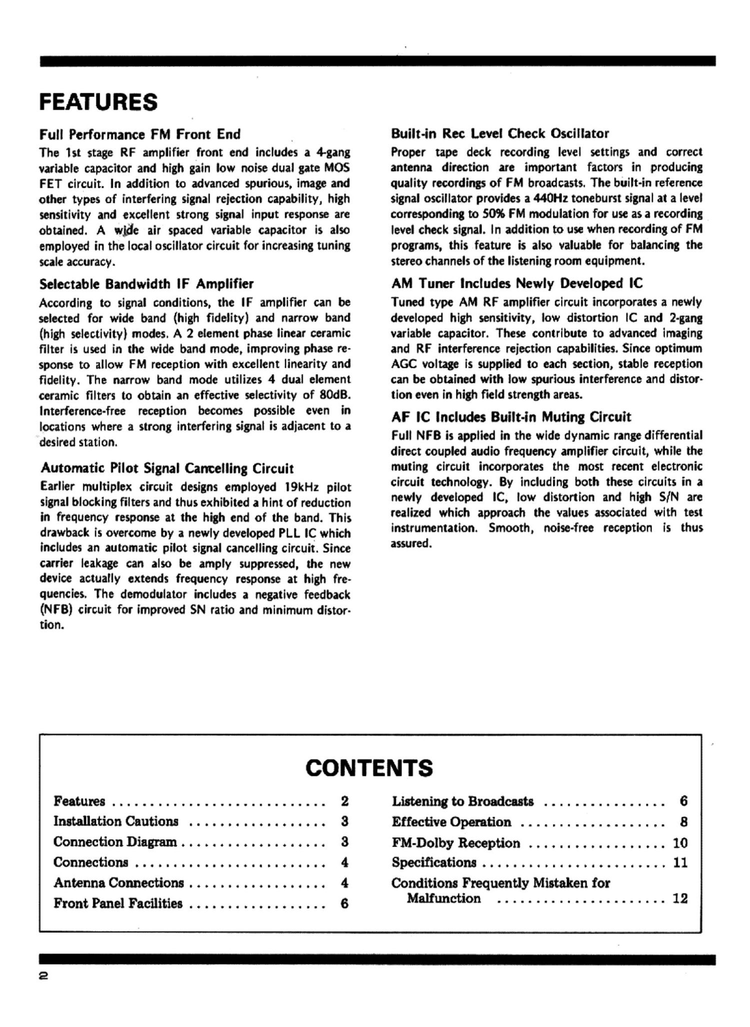
FEATURES

Full Performance FM Front End

The 1st stage RF amplifier front end includes a 4-gang
variable capacitor and high gain low noise dual gate MOS
FET circuit. In addition to advanced spurious. image and
other types of interfering signal reiection capability, high
sensitivity and excellent strong signal input response are
obtained. A wide air spaced variable capacitor is also
employed in the local oscillator circuit for increasing tuning
scale accuracy.

Selectable Bandwidth lF Amplifier

According to signal conditions, the IF amplifier can be
selected for wide band (high fidelity) and narrow band
(high selectivity} modes. A 2 element phase linear ceramic
filter is used in the wide band mode, improving phase re-
sponse to allow FM reception with excellent linearity and
fidelity. The narrow band mode utilizes 4 dual element
ceramic filters to obtain an effective selectivity of 80dB.
Interference-free reception becomes possible even in
locations where a strong interfering signal is adjacent to a
desired station.

Automatic Pilot Signal Cancelling Circuit

Earlier multiplex circuit designs employed l9kHz pilot
signal blocking filters and thus exhibited a hint of reduction
in frequency response at the high end of the band. This
drawback is overcome by a newly developed PLL lC which
includes an automatic pilot signal cancelling circuit. Since
carrier leakage can also be amply suppressed. the new
device actually extends frequency response at high fre-
quencies. The demodulator includes a negative feedback
(NF B) circuit for improved SN ratio and minimum distor-
tion.

Built-in Rec Level Check Oscillator

Proper tape deck recording level settings and correct
antenna direction are important factors in producing
quality recordings of FM broadcasts. The built-in reference
signal oscillator provides a OH: toneburst signal at a level
corresponding to 50% FM modulation for use as a recording
level check signal. in addition to use when recording of FM
programs. this feature is also valuable for balancing the
stereo channels of the listening room equipment.

AM Tuner Includes Newly Developed IC

Tuned type AM RF amplifier circuit incorporates a newly
developed high sensitivity, low distortion lC and 2-gang
variable capacitor. These contribute to advanced imaging
and RF interference rejection capabilities. Since optimum
AGC voltage is supplied to each section, stable reception
can be obtained with low spurious interference and distor-
tion even in high field strength areas.

AF IC includes Built-in Muting Circuit

Full NFB is applied in the wide dynamic range differential
direct coupled audio frequency amplifier circuit, while the
muting circuit incorporates the most recent electronic
circuit technology. By including both these circuits in a
newly developed IC, low distortion and high SIN are
realized which approach the values associated with test
instrumentation. Smooth, noise-free reception is thus
assured.

Features ............................ 2
InstallationCautions.................. 3
ConnectionDiagram........ ..... 3
Connections........... ..... 4
AntennaConnections. . ...... 4
Front Panel Facilities .................. 6

CONTENTS

Listening to Broadcasts ................ 6
Effective Operation ................... 8
IM-Dolby Reception ..... . ............ 10
Specifications . . . . ................ 11
Conditions Frequently Mistaken for
Malfunction ...................... 12

Page 2

-PIONEER

INSTALLATION CAUTIONS

To ensure long term reliable performance, avoid installing the TX-SBOOI] in locations such as the following:

Loations to In evoided

Possible detrimentei efleets

e Direct sunlight. redletors or other heet some. Above or neer
high power stereo emolifiers or power trensformets.

eSim subject ,to poor ventilation, high humidity or moisture.

e Dusty Iocetions
e Where AM redio or TV set is being used simulteneouelv.

e Locetione where elcohol. insect sprevs or voletile meterieis ere
u-d or stored.

e Externel heetino cen ceuse deterioretion of circuit components
end mey prevent stebie operetion.

OCorrosion of terminel contects which cen lead to leulty connec-
tions. Humidity end moisture cen elso ceuse defective ineuietiOn,
present the ridt of leekeoe currents end overheeting of circuit
components.

0 lnternel ecoumuietions of dust cen ebsorb moisture end Ieed to
teulty insuietion.

eMutuel interference cen occur from oscillator circuits used in
the. products.

e Appeerence end finish of front penel con be demeoed.

CONNECTION DIAGRAM mu-«www-«ac-unawummnnnum

FM DE-EMPHASIS SWITCH , AM ANTENNA

Normeliy, set this switch to "75m."
Be sure to set it to "25m, only when
listening to en FM broedeest (9'0-
emphesie: 25m) with e Dolby system.
See page 10.

iindoor or outdoor)

WT

P----------

T TYPE FM OUTDOOR
FM ANTENNA ANTENNA
(if stetions ere MGM) DISCRETE 4-CHANNEL

FM ADAPTOR

TX 85"

L, r-

f I. sumo}

0
~13: ::::
9 l

l-_...___J

KM Fennn'e m ANTENNA


OUTLET (not
coupled with
power switch!

DC "LIV-j

MW
noon-nee H

CONVENIENCE h

GROUND

$0 LLOSCOPE

' The word "Dolby" is a trademark of Dolby Laboratories Inc.


oorooiszoo
i-o "0990 ll
sreaeo AMPLIFIER

n.
,r 1.3.199 i».
TAPE DECK