Pioneer tx 710 l owners manual

This is the 8 pages manual for pioneer tx 710 l owners manual.
Read or download the pdf for free. If you want to contribute, please mail your pdfs to info@audioservicemanuals.com.

Page: 1 / 8
left right
pioneer tx 710 l owners manual

Extracted text from pioneer tx 710 l owners manual (Ocr-read)


Page 1

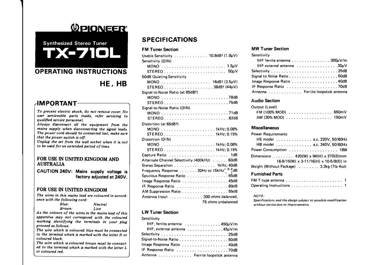
Synthesized Stereo Tuner

TX-7'IOL

OPERATING INSTRUCTIONS
HE. HB

(IMPORTANT

To prevent electric shock, do not remove cover. No
user serviceable parts inside, refer servicing to
qualified service personnel.

Always disconnect all the equipment from the
mains supply when disconnecting the signal leads.
The power cord should be connected last, make sure
that the power switch is off.

Unplug the set fi-om the wall socket when it is not
to be used for an extended period of time.

FOR USE IN UNITED KINGDOM AND
AUSTRALIA

CAUTION 240V: Mains supply voltage is
factory adjusted at 240V.

FOR USE IN UNITED KINGDOM

The wires in this mains lead are coloured in accord-
ance with the following cord:

Blue: Neutral

Brown: Live
As the colours of the wires in the mains lead of this
apparatus may not correspond with the coloured
marking identifying the terminals in your plug
proceed as follows,
The wire which is coloured blue must be connected
to the terminal which is marked with the letterN or
coloured black.
The wire which is coloured brown must be connect-
ed to the terminal which is marked with the letter L
or coloured red.

SPECIFICATIONS

FM Tuner Section

Usable Sensitivity ............. 10.8dBf (1 .QuV)
Sensitivity (DIN)

MONO ........................ 1.5pV

STEREO ........................ 50pV
SOdB Quieting Sensitivity

MONO ................... 16dBf (3.5uV)

STE REO ................... 38dBf (44uV)
Signal-to-Noise Ratio (at BSdBf)

MONO ......................... 78dB

STEREO ......................... 75dB
Signal-to-Noise Ratio (DIN)

MONO .......................... 71dB

STEREO ........................ 62dB
Distortion (at 65d8f)

MONO ..................... 1kHz; 0.03%

STEREO .................... 1kHz;0.15%
Distortion (DIN)

MONO ..................... 1kHz; 0.08%

STEREO .................... 1kHz;D.15%
Capture Ratio ....................... 1dB
Alternate Channel Selectivity (400kHzi ...... BDdB
Stereo Separation ................ 1kHz; 40dB
Frequency Response ,,,,,,, 20Hz to 15kHz_°':dB
Spurious Response Ratio ................ SSdB
Image Response Ratio .................. 45d8
IF Response Ratio ,,,,,,,,,,,,,,,,,,,, SOdB
AM Suppression Ratio .................. 55dB
Antenna Input ............. 300 ohms balanced,

75 ohms unbalanced

LW Tuner Section
Sensitivity
IH F , ferrite antenna .............. 450uV/m
IH F, external antenna .............. 45uV/m
Selectivity .......................... 25dB
Signal-to-Noise Ratio ................... SOdB
Image Response Ratio .................. 40dB
IF Response Ratio .................... 70dB

Antenna ............. Ferrite loopstick antenna

MW Tuner Section

Sensitivity

IH F ferrite antenna ............... SOOuV/m

IHF external antenna ............... 30uV
Selectivity .......................... 25dB
Signal to Noise Ratio ................... SOdB
Image Response Ratio .................. 40dB
IF Response Ratio .................... 70dB
Antenna ............. Ferrite loopstick antenna

Audio Section
Output (Level)

FM (100% MOD) ................. 650mV
AM (30% MOD) .................. 150mV
Miscellaneous
Power Requirements
HE model ........... . . . a.c. 220V, 50/60Hz
HB model .............. a.c. 240V, 50/60Hz
Power Consumption ................... 16W
Dimensions ........ 420(W) x 94(H) x 270(Dimrn
16-9/16(W) x 3-11/16(H) x 10-5/B(D) in
Weight (Without Package) ........ 3.3kg (7|b 4oz)
Furnished Parts
FM T-type antenna ...................... 1
Operating Instructions .................... 1
NOTE:

Specifications and the design subject to possible modification
without notice due to improvements.

Page 2

TROUBLESHOOTING

Sometimes an operational fault can be mistaken for a malfunction or failure. Check the following points and see if
the symptoms of the trouble are outlined below before you get in touch with the servicemen. If you cannot locate
the symptoms, turn off the power and contact your nearest Pioneer Service Center, Service Station or authorized

Pioneer dealer.

Symptom

Diagnosis check point:

Remedy

No sound

Power switch is STAND-BY.

Power plug is not connected to the power out-
let.

Set to ON.

Connect the plug to the outlet securely.

Cannot receive FM
station.

Function switch does not correspond to the
correct frequency band.

The antenna connecting leads hava worked free.

The input signal level is weak

The signals being picked up are weak and so the
muting circuit has been activated and no sound
is heard.

Set the function switch to the correct fre-
quency band.
Connect firmly to the terminals.

When the FM LOCAL switch is set to ON, try
resetting it to OFF and depressing the TUNING
switch.

Install a highly sensitive antenna outdoors.

Cannot receive AM
station.

Function switch does not correspond to the
correct frequency band.

Signal indicators do not work properly indicat-
ing that signal strength is insufficient.

Set the function switch to the correct fre-
quency bend.

Try changing the position of the bar antenna
or install an outdoor antenna.

Cannot receive
programmed
station even when
the station call
switch is
depressed.

Function switch does not correspond to the
correct frequency band.

Power cord has been disconnected for a long
time (more than 3 days) and so contents of
memory have been erased.

Set the function switch to the correct fre-
quency bands

Perform memory operation again.

Memory function
does not work

After memory indicator goes off. station call
switches are depressed

Depress the station call switch immediately
after depressing the memory switch again.

Intermittent noise
or sound is
distorted

The FM antenna is being affected by the multi-
peth phenomenon.

Point the FM antenna properly in the direction
of the transmitting antenna.

NOTE

The specifications of this model differ according to the ship-

ment destination.

e For U. K. (H8 stamped on pecking case); Power line voltage
is 240 volts.

0 For mainland Europe {HE stamped on pecking meal; Power
line voltage is 220 volts

Model: have their line voltage; set in accordance with their

destinatrbn before they are shipped from the factory. The volt-

age which has thus been set is indicated on the rear panel of the

main unit.

Before switching on the power, make absolutely sure that the

voltage tallies with the value used in your area. If it does not

tally or if you move to another area with a different voltage

(such from 220V to 240V or vice versal, get in touch with your

nearest authorized Pioneer Service Center or Service Station or,

alternatively, call for a qualified electrician to set the voltage

properly.

PIONEER ELECTRONIC CORPORATION 4-1. Megum 1-Chome. Meguco-kU-Tokvo 153. Japan
us. FIONEER ELECfnomca conpmA'rluN 55 Oxford Drlve. Moonscme. New Jersey 07074. U 3A
mouse: ELEcrnonm: stumps) N.V. Lulthagen-Haven 9. 2030 Ancwenp. Belgium

FIONEER ELECTRGIICB AUSTRALIA PTY.LTO. 175-154 Boundary Fitted. Braaslda. Vicmrla 3195. Australia

Printed in Belgium (ARE-376-0>