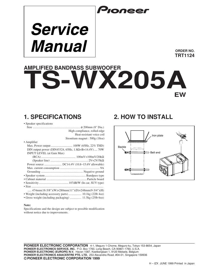
Pioneer tswx 205 a service manual

This is the 10 pages manual for pioneer tswx 205 a service manual.
Read or download the pdf for free. If you want to contribute, please mail your pdfs to info@audioservicemanuals.com.

Page: 1 / 10
left right
pioneer tswx 205 a service manual

Extracted text from pioneer tswx 205 a service manual (Ocr-read)


Page 1

Pioneer

Service
Manual

TRT1124

AMPLIFIED BANDPASS SUBWOOFER

TS-wxzosg

1. SPECIFICATIONS 2. HOW TO INSTALL

- Speaker specific ions

Size ......................................................... (1) 200mm (8" Dia.)
High compliance, rolled edge _
Heateresistant voice coil Iron plate %
Strontium magnet : 500g (18oz) \
- Amplifier / l/ I I (1
Max. Power output ............................ 100w (65Hz, 22% THD) Backle

DIN output power (DIN45324, 65H; l.8Q+B=l4.4V) 70W
INPUT LEVEL (at Gain Max)
(RCA) .....
(Speaker line)
Power source .....
Max. current consumption
Grounding .....
' Speaker system
' Cabinet material
- Sensitivity ........

Belt end
. 100mV+100mV/20k§2
.............. 2V+2Vl5kfl
. DCI4.4V (10.8~15.6V allowable)


107dB/W (In car, SUV type)

- Size ..................................................................................

..... 474mm(1875/8)(W)><280mm(l l)(D)X24Smm(9A 4 )(H)
' Weight (including accessory parts) ................. 10.1kg (22: 4oz)
Gross weight (including packaging) ............... 11.5kg (251b 6oz)
Note:

Specifications and the design are subject to possible modification
without notice due to improvements.

PIONEER ELECTRONIC CORPORATION 4-1, Meguro 1-Chome, Meguro-ku, Tokyo 153-8654, Japan
PIONEER ELECTRONICS SERVICE, INC. P.O. BOX1760, Long Beach, CA 90801-1760, U.S.A.

PIONEER ELECTRONIC (EUROPE) N.V. Haven 1087, Keetberglaan 1, 9120 Melsele, Belgium

PIONEER ELECTRONICS ASIACENTRE PTE. LTD. 253 Alexandra Road, #04-01, Singapore 159936

©P|ONEER ELECTRONIC CORPORATION 1999
H - IZX JUNE 1999 Printed in Japan

Page 2

TS-WX205A

3. EXPLODED VIEWS AND PARTS LIST

NOTES: 0 Parts marked by "NSP are generally unavailable because they are not in our Master Spare Part3 List.
. The A markfaund (m mme campanentparts indicate? the importance of the Safety factor of the part.

Therefore, when replacing, be sure to me parts of identical designation.

. Screwx adjacent to V mark an the product are asedfor dixaxxembly.

3.1 MAIN UNIT

0 MAIN UNIT PARTS LIST

Mark No. Description Part No. Remark Mark No. Description Part No. Remark

1 Woofer 20-211AZ x1 8 Screw BNC40P300FNI x4
NSP 2 AMP UNIT TWK1010 x1 9 Heat Sink TNA1515 ><1
NSP 3 SWITCH UNIT TWS1028 x1 10 Shield Plate TNA1517 X1

4 Cabinet Assy TXC1145 x1 11 Terminal Panel TNS1018 x1

5 Screw TBA1121 x10 12 Screw BBZaDP080FMC x11

6 Cord TDC2260 x1 13 Screw PBB30P14OFMC x2

7 Screw BNC40P200FMC x6 14 PCB Unit TWX1025-AZ ><1