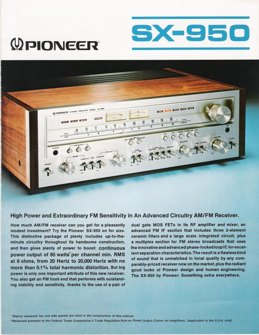
Pioneer sx 950 brochure

This is the 6 pages manual for pioneer sx 950 brochure.
Read or download the pdf for free. If you want to contribute, please mail your pdfs to info@audioservicemanuals.com.

Page: 1 / 6
left right
pioneer sx 950 brochure

Extracted text from pioneer sx 950 brochure (Ocr-read)


Page 1

an 5x sen

MFIONEER svznzo nzczwzn

High Power and Extraordinary FM Sensitivity in An Advanced Circuitry AM/FM Receiver.

How much AM/FM receiver can you get for a pleasantly
modest investment? Try the Pioneer SX-950 on for size.
This distinctive package of plenty includes up-to-the-
minute circuitry throughout its handsome construction,
and then gives plenty of power to boost: continuous
power output of 85 wattsper channel min. RMS
at 8 ohms, from 20 Hertz to 20,000 Hertz with no
more than 0.1% total harmonic distortion. But big
power is only one important attribute of this new receiver.
You also get an FM tront end that performs with outstand-
ing stability and sensitivity, thanks to the use of a pair of

dual gate MOS FETs in its RF amplifier and mixer, an
advanced FM IF section that includes three 2-element
ceramic filters and a large scale integrated circuit, plus
a multiplex section for FM stereo broadcasts that uses
the innovative and advanced phase-locked loop IC for excel-
lent separation characteristics. The result is a flawless kind
of sound that is unmatched in tonal quality by any com-
parably-priced receiver now on the market, plus the radiant
good looks of Pioneer design and human engineering.
The SX-950 by Pioneer: Something extra everywhere.

'Walnut veneered top and side panels are used in the construction of this cabinet.
*Measured pursuant to the Federal Trade Commission's Trade Regulation Rule on Power Output claims tor Amplifiers. (Applicable to the U.S.A. only)

Page 2

SX-SEO

WIDE DYNAMIC RANGE EOUALIZER
FOR FLAT RECORD REPRODUCTION

Because a high voltage of plus»minus
split power (+25V, -16V) is supplied
to the equalizer circuit of the SX-950,
the phono overload level is extended to
200mv (1 kHz, T.H.D. 0.1%) against ar
input sensitivity of 2.5mV. This indicates
that the equalizer circuit has sufficient
dynamic margin to reproduce records,
possessing a wide dynamic range at
minimal distortion, even when large out-
put voltage cartridges are used for
record reproduction. The equalizer cir-
cuit is composed of a 3-stage direct-
coupled design with a 1-stage PNP to
achieve high gain amplification and to
offer low distortion by applying sufficient
NFB (Negative Feedback). Because
selected parts for the RIAA elements
enable flat record reproduction, RlAA
deviation is precise within $0.3dB. Such
precision prevents sound coloration
throughout the equalizer section.

PHONO OVERLOAD LEVEL

INPUT TERMINAL PHONO
OUTPUT TERMINAL REc OUT
; DUMMY LOAD 47 Kohms
* T H D 01:

INPUT LEVEL IN IIIv

6
4

2

i0 2 45100 2 451k 2 46m 2 46
FREQUENCY IN Hz

EOUALIZER RIAA DEVIATION

INPUT TERMINAL PHONO
OUTPUT TERMINAL REC OUT
DUMMY LOAD 47 Kchms

FREQUENCV RESPONSE W as

i0 2 46100 2 Aeik 2 Aetok 2 46
FREQUENCV IN Hz

TWO-STEP TURNOVER TONE
CONTROL AND FLAT AMPLIFIER,
USING 1-STAGE FET

3A5: TREBLE
-I F- '1 1

vwmvu «m mum.

; «ref-r
/. .

The SX-950 uses an FET in the first stage
of its flat amplifier to minimize noise that
could occur when the volume level is
altered. Additionally, an independent
turnover frequency selector is provided
for each of the tone controls for BASS
and TREBLE with a turnover frequency
of 200Hz or 400Hz used in the bass
range and 2.5kHz or SkHz in the treble
range. The tone ON/OFF switch can be
used to bypass the tone control circuit
instantly so that the effectiveness and
versatility of the tone control are en-
hanced-it can be checked or a flat
sound reproduction can be achieved.

TONE CONTROL


INPUT TERMINAL AUX
OUTPUT TERMINAL: SPEAKER
DUMMY LOAD 3 Ohms

L
n

+
m

I
s

A

QUENCV RESPONSE lN ca
aa o

TURNOVER FREQUENCY
BASS 200Hz
TREBLE 5I

FRE

1024600246 2A6

FREQUENCY IN Hz

iOk2 46

TONE CONTROL
INPUT TERMINAL: AUX
OUTPUT TERMINAL SPEAKER
DUMMY LOAD 5 Ohms

I_.
mm

I
A

5

I
no

TURNOVER FREQUENCY
RAss AOOHz
TREELE 2,5kH2
I02 461002 45w 2 46ka2 46
FREQUENCY IN Hz

FREQUENCY RESPONSE IN OE
o

LOW-CUT, HIGH-CUT FILTERS

Cut-off frequency for the low filter is
SOHz and it is 6kHz for the high filter.
Both filters have sharp curve character-
istics of 6CIB/oct and thus can cut
unnecessary frequency range without
impairing tonal quality.

BIG OUTPUT POWER AMPLIFIER

SECTION WITH LOW DISTORTION
AND HIGH SIN

The all-stage direct-coupled OCL circuit
with 1-stage PNP differential amplifier

delivers continuous power out-
put of 85 watts* per channel
min. RMS at Sohms, from 20
Hertz to 20,000 Hertz, with no
more than 0.1% total harmonic

diSIOI'fiOI'l. A 1-stage PNP differential
amplifier improves DC stability by acti-
vating sufficient negative feedback. The
constant current load adopted in the
pre-driver also saves DC loss and as-
sures a low distortion performance over
an unusually wide range while also
achieving high gain amplification in the
lineararea ofthetransistors.The parallel
push-pull circuit in the output stage,
which minimizes even numbered har-
monicdistortionassuresawide dynamic
range from small signals to the big
pulsive signals.

POWER OUTPUT Vs TOTAL HARMONIC DIsToRTION
II I I II I I I -

* INPUT TERMINAL POWERAMPIN

z

2 OUTPUT TERMINAL SPEAKER l I

9 Di fl DUMMV LOAD BOWHS

E OPERATlDN BOTH CH DRiVEN I

I9 4 ___ I , A"
I.» \ at. . . ~ _,
9 2 7

5001 i

E 5.7 A, s :
i 4 " 20Hz E
1 , - ikHz ,
E 2 eeeeee ZOkHz A
,_

com i i i

N4
s4
0,4

(M 2 45m 2 4610 2 ASIUO
POWER OUTPUT IN WATTS

POWER OUTPUT vs TOTAL HARMONIC DISTORTION
I

i . ir-t

o

INPUT TERMINAL AUX
7 OUTPUTTERMINAL SPEAKER 7
DUMMY LOAD 5 Ohms 777777 aokHz A

OPERATION BOTH CH DRIVEN
DO.t_I_II#I_I_I_.U_I_I_I_IU_I_II_

m2 45H) 2 46i0 2 450302 45
POWER OUTPUT lN WATTs

77* 20Hz
ikHz

o
mbmgmbm

OTOTAL HARMONIC DISTORTION IN "0

Measured pursuant to the Federal Trade Commission's