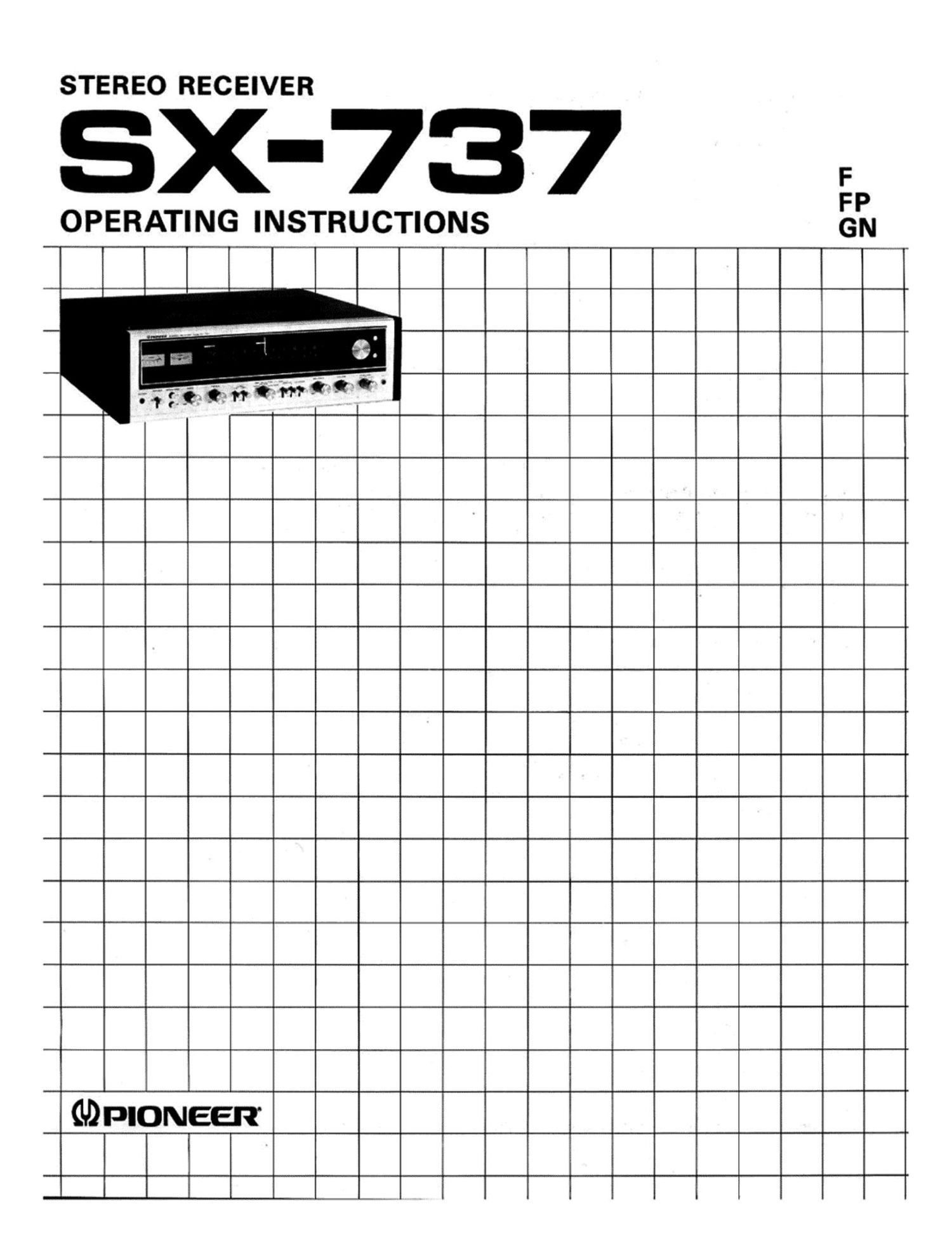
Pioneer sx 737 owners manual

This is the 16 pages manual for pioneer sx 737 owners manual.
Read or download the pdf for free. If you want to contribute, please mail your pdfs to info@audioservicemanuals.com.

Page: 1 / 16
left right
pioneer sx 737 owners manual

Extracted text from pioneer sx 737 owners manual (Ocr-read)


Page 2

FEATURES

Advanced Tuner Section

0 FM tuner section using high stability circuitry.

0 FM front end with dual gate MOS FET and rectilinear
frequency four-stage variable capacitor.

0 IF amplifier circuitry with high reliable integrated
circuits developed by Pioneer.

0 incorporation of two twin-element phase-linear ceramic
filters and high stability circuitry components makes for
excellent image rejection, superior capture ratio, im-
proved S/N ratio plus selectivity - in short, tip«top
performance all round.

0 Phase Locked Loop circuin is used in the multiplex
circuit to prevent deterioration due to temperature
changes and the passage of time.

0 Pioneers low distortion and excellent separation
characteristics provide for stable operation which
ensures enhanced FM stereo listening pleasure for you.

Low Distortion, Wide Range Power Amplifier.

Thanks to the use of extra-reliable NPN and PNP silicon
power transistors and a differential one-stage, completely
and superior frequency characteristics are assured.
Moreover, the output range and the distortion characte-
ristics are greatly improved.

The differential amplifier circuit and the temperature
compensation circuit further ensure that the stability and
superior performance of the Receiver are not subject to
external conditions, and this adds up to extra stereo
listening pleasure for the customer.

High Fidelity Preamplifier

The utilization of the finest components available in the
equalizer circuit keeps deviation from the RlAA standards
down to a minimum, thereby making an important contri-
bution to the faithfulness of record reproduction. Also, the
three-stage direct coupled amplifier circuitry which uses
low noise silicon transistors and a balanced positive-negative

power supply, plus the high permissible input level, broaden
the dynamic range considerably.

Therefore distortion is reduced and true high fidelity disc
reproduction is made possible.

Components Protected by Safety Circuit

The protection circuit, which combines electronic circuitry
and relays and functions instantaneously, means that the
speakers and transistors are protected from damage which
might otherwise have resulted from all kinds of faulty
connections or the shorting of the speaker terminals.

A Recording Selector Switch include Specially
for Recording Fans

While you are listening to sound from speakers according
to any mode you have set with the FUNCTION switch,
a tape deck connected to the TAPE 1 jacks on the back
panel can record such other program sources as a disc or
FM broadcast selected by the REC SELECTOR switch.

A Receiver which can Handle any Program Source

Amongst the input jacks on the back panel are turntable
and auxiliary connectors, two separate tape deck terminals
(for cassette decks or open-reel decks) plus microphone
jack on the front panel, so that any source whatever can be
utilized to provide flexible listening pleasure.

Two Sets of Speaker Systems may be Connected

This Receiver is furnished with two sets of speaker
terminals on the back panel and the corresponding posi-
tions on the speaker selector switch. Thus you can play
whatever music you are listening to through two pairs of
speaker systems at once, so you can have the same program
playing in two separate rooms simultaneously.

Advanced Uitramodern Design

The entire design of this Receiver has been carefully
thought out with efficient functioning in mind.

The entirely new-look SX-737 will fit in with the decor of
your listening room perfectly, thanks to its tasteful wooden
cabinetry and top quality appearance.

CONTENTS

Line Voltage and Fuse and Rear Panel ....... 3
Placement ....... . ..................... 3
Stereo System Setup ..................... 4
Speaker System Connection ............... 4
Connection Diagram ..................... 5
Antenna and Ground Connections .......... 6
Equipment Component Connections ........ 7

Front Panel Facilities .................... 8
How to Operate the Receiver .............. 10
About 4-channel Stereo System ............ 12
Conditions Frequently Mistaken for

Malfunction ......................... 13
Specifications .......................... 14
Mounting Template ..................... 15