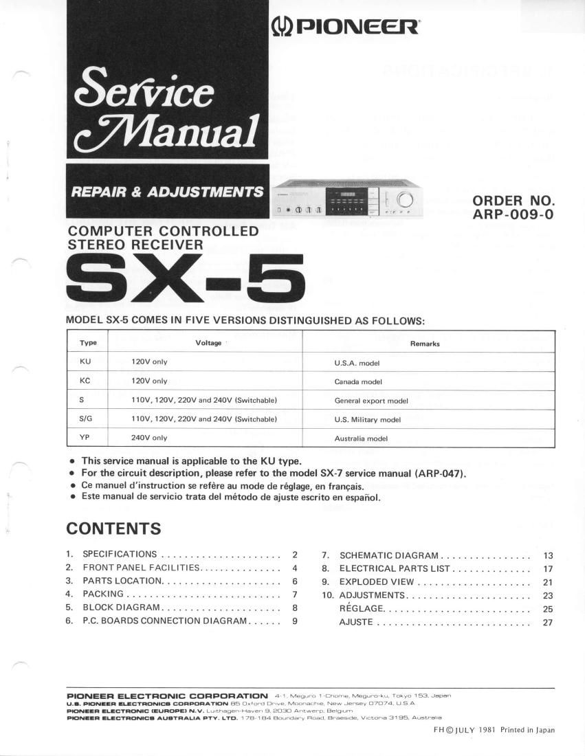
Pioneer sx 5 service manual

This is the 28 pages manual for pioneer sx 5 service manual.
Read or download the pdf for free. If you want to contribute, please mail your pdfs to info@audioservicemanuals.com.

Page: 1 / 28
left right
pioneer sx 5 service manual

Extracted text from pioneer sx 5 service manual (Ocr-read)


Page 1

1. SPECIFICATIONS Amplifier Section Continuous Average Power 0utput is 30 watts* per channel, min., at 8 ohms from 20 Hertz to 20,000 Hertz with no more than 0.02 % total harmonic distortion. Total Harmonic Distortion (2O Hertz to 20,000 Hertz, 8 ohms, from AUX/VIDEO) continuous rated power output . . No more than 0.02% 15 watts per channel power output No more than 0.027o f ntermodulation Distortion (50 Hertz; 7,000 Hertz = 4 : 1, 8 ohms, from AUX/VIDEO) continuous rated power output . . No more than 0.02% Damping Factor (20 Hertz to 20,000 Hertz, 8 ohms) I n put (Sensitivity/l mpedance) PHONO ..2.5mV/50kilohms TUNER, AUX/VIDEO, TAPE PLAY 150mV/50 kilohms Phono Overload Level (T.H.D. O.1%, 1,000H2) PHONO 130mV Output ( Level/l mpedance) TAPE REC .15OmYl22 kilohms Frequency Response PHONO (RIAA Equalization) 30Hz to 15,000H210.3d8 TUNER, AUX/VIDEO, TAPE PLAY . . . . 1OHzto 50,000H21!'uoe Tone Control BASS. ..18d8(100H2) TREBLE . .18d8 (10kHz) Loudness Contour (Volume control set at -4OdB position) . . +6dB (100H2) Hum and Noise (lHF, short circuited A network) PHONO . . .76d8 AUX/VIDEO,TAPEPLAY. ....96d8 FM Tuner Section Usable Sensitivity . Mono; 11.2dBf (lHF) (1.OpV,75 ohms) 50dB Ouieting Sensitivity . . . . 16.3dBf (1.8pV, 75 ohms) Stereo; 37.zd9f (19.9pV, 75 ohms) Signal-to-Noise Ratio Mono;75d8 (at 85dBf) Stereo;70dB (at 85dBf) Distortion (at 65dBf) Mono. ...100H2;0.15% lkHz:0.15o/o 6kHz:O.2o/o Stereo ....100H2; 0.3% lkHz; O.3o/o 6kHz:O.4o/o CaptureRatio. ....1.0dB AlternateChannelSelectivity .. .. 400kHz;60dB 50 StereoSeparation. ... lkHz;4OdB 30Hz to 15kHz;35dB Frequency Flesponse 2OHz to l5kHz +0.5d8, -1dB SpuriousResponseRatio. ...65d8 lmage Response Ratio .65dB lF Response Ratio . . .90d8 AM Suppression Ratio . 55dB SubcarrierProductRatio. ...40d8 SCA Rejection ratio . 60dB Muting Threshold . . 29.3dBf (8pV) Antenna Input . . 300 ohms balanced, 75 ohms unbalanced AM Tuner Section Sensitivity lHF, ferrite antenna . . 300pV/m lHF, external antenna 15pV Selectivity ....27d8 Signal-to-NoiseRatio ..50d8 lmage Response Ratio . 40dB lFResponseRatio. ..73d8 Antenna Built-in ferrite loopstick antenna Miscellaneous Power Requirements AC 120V, 60Hz PowerConsumption ...200W(UL) Dimensions . 420(W) x 98(H) x 311(D) mm 16-9/16(W) x 3-7l8(H) x 12-114(Dl in Weight (without package) . . . . 5.8 kS (12lb 13oz) Furnished Parts FM T-type Antenna 1 DryBatterySUM-3"AA" . ....2 StationCard. ......2 Operating Instructions 1 *Measured pursuant to the federal Trade Commission's Trade Regulation rule on Power Output Claims for Amplifier. NOTE: Specifications and design subject to possible modification without notice-

Page 2

SETTING USE THE AM CHANNEL STEP SWITCH (on the rear panel) Before the receiver leaves the manufacturing plant, this switch is set to the channel allotment plan of the destina- tion. For the U.S.A.. it is set to 1OkHz. Check that the switch is set properly before use. Set it to the 9kHz position when the channel allotment plan is changed and the intervals between the AM broad- casting stations change from 1 OkHz to 9kHz units. NOTE:Contact your dealer and inquire if you are not sure about the chan nel al I otment pla n. LOADING THE BATTERIES Two size "AA" dry batteries are provided as accessories. They are used to retain the station presetting memory functions. Before using the unit, disconnect the power cord and load the batteries into the compartment on the rear panel as follows: 1. Slide the lid in the direction of the arrow and oDen the compartment (see Fig. 1). 2. Load the batteries with the polarities properly aligned with the marks on the inside of the compartment (see Fis. 2). 3. Align the tab of the lid with the interlocking hole and depress the lid lightly. Battery Precautions: lf batteries are incorrectly used, they may leak or even break open inside the battery holder. Observe the following precautions when inserting and replacing the batteries. 1. Always be sure the + and - ends are aligned properly as shown above and as marked on the battery holder. 2. Do not use new batteries and partly used batteries at the same time. 3. Do not use different brands and types of batteries at the same time. CHANNEL STEP f-Iil iTil ?? 9lHr J LtOrHz l OkHz position Fis.2 Insert tab into interlocking hole Fis. 3 Fis.4 There are rechargeable dry cell batteries and non- rechargeable dry cell batteries. Always read the notes on the battery to be sure which kind you have. When replacing the batteries, always use the same type of batteries (carbon zinc) as the ones originally provided with the receiver. Do not use alkaline and nickel cad- mium type batteires. 4. 5. 3