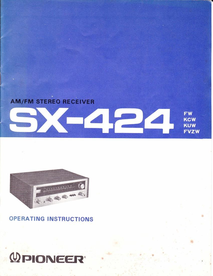
Pioneer sx 424 owners manual

This is the 12 pages manual for pioneer sx 424 owners manual.
Read or download the pdf for free. If you want to contribute, please mail your pdfs to info@audioservicemanuals.com.

Page: 1 / 12
left right
pioneer sx 424 owners manual

Extracted text from pioneer sx 424 owners manual (Ocr-read)


Page 1

Welcome to the proud family of owners of Pioneer Hi-Fi equipment! Your new SX-424 AM/FM Stereo Receiver opens up a whole variety of magnificent listening experiences including FM stereo reception, record and tape playing, tape recording, and many more. You can even use it as a public address sys- tem for parties and speeches by plugging in a micro- phone. FEATURES FM STEREO TUNER WITH FET-EOUIPPED FRONT END The FM tuner's RF amplifier stage is equipped with a field effect transistor (FET), resulting in higher sensitivity, better selectivity and image rejection as wel I as greater freedom from disturbing cross-modulation. The FM MPX (stereo) decoder circuit operates on the highly accurate,time switch- ing principle assuring clear-cut stereo channel separation and high operational stability. SENSITIVE AM RECEPTION WITH BUILT-IN FERRITE BAR ANTENNA An external AM antenna will not be needed in most cases, because the built-in ferrite antenna assures high sensitivity. EASY TUNING WITH SIGNAL STRENGTH METER AND LARGE DIAL Tuning on both FM and AIVI is quick and accurate, thanks to the illuminated signal strength meter and the large, linear (FM) tuning dial. LINE VOLTAGE AND FUSE The SX-424 is available in two models: one model operates only on 120V, and the other either of five line voltages: 110V, 720V, 130V, 220Y and 240V.If your SX-424 is the latter model, set the unit to the proper line voltage as follows: CHANGING LINE VOLTAGE SETTING AND FUSE To remove the fuse, turn the fuse cap located on the line volt- age selector in the direction of the arrow. Then remove the fuse plug from the unit. Put the fuse plug back so that the proper line voltage marking can be seen through the cut in the edge of the plug Whenever the position of the selector is changed, check the rating of the fuse. A 1A fuse is to be used for either 220Y or 240Y operution and a 2A fuse for 110V, 120V or 1-30V operation. If the rating of the fuse is correct, replace the cap. FUSE REPLACEMENT When the fuse blows, remove the fuse cap and replace the fuse with a new one. See Fig. 1. Combine the SX-424 with other components of equally high quality turntable, tape deck, speakers - study the operating instructions care- fully, and start off into a whole new world of excit- ing sound. CONVERTIBLE INTO A 4-CHANNEL STEREO SYSTEM By adding the Pioneer 4-channel decoder amplifier, model OL-600A and two npre speaker systems the SX-424 can be upgraded into an ultra-modern "4-channel stereo" sound system with both matrix and discrete 4-channel capab ilities. PROVISIONS FOR ALL COMMON PROGRAM SOURCES One turntable, one stereo tape deck and one auxiliary source (such as a cassette or cartridge tape player, etc.) can be connected to the SX-424. ALSO SERVES AS MICROPHONE AMPLIFIER By connecting a microphone, the SX 424 can be used as a public address system for speeches, announcements, etc. STYLED WITH CHARACTERISTIC PIONEER ELEGANCE The functional and at the same time attractive metallic front panel and natural wood cabinet are impressive-looking and bezutifully matched to the styling of other Pioneer Hi-Fi components. corN Fig. 1

Page 2

TJIONEEFI ASSEMBLING A STEREO SYSTEM Model SX-424 is a Stereo Receiver. To obtain a complete stereo system, it can be combined with 2 or 4 speaker systems, 1 turntable, 1 tape deck, etc. See Fig. 2. With the help of the Pioneer "4-channel decoder" ampli- fier, model QL-600A and an additional pair of speaker systems, the SX-424 can serve as the heart of an ultra- modern 4-channel stereo system. See Fig.3. INSTALLATION Do not instali the SX-424 in the following places: o In direct sunlight or near heating units. o In damp, dusty places or where air circulation is poor. o In vibration-prone, unstable places. CONNECTION AND INSTALLATION OF SPEAKER SYSTEMS CONNECTION o As shown in Fig. 4, connect the lead wires of the speaker systems to the supplied speaker plugs. Be sure to observe the correct polarity and to cause no short between @ and o. o For the main set of speaker systems, use the A speaker sockets. Connect the right-channel speaker system to the socket marked R, and the left-channel speaker system to the socket marked L. o For a second set of speaker systems, use the B speaker sockets. Connect in the same way as for the first set. NOTE: When using two pairs of speaker systems simultaneously {with the SPEAKERS switch set to A+B), make sure that the impedance of each set is at least 8f,1. INSTALLATION Optimal stereo effect is obtained when the listener is at one corner of a regular triangle whose base is the line connecting the left and right speaker systems (approx. B ft to 8 ft apart). If at all possible, place the speaker systems at the same height: a great difference in height affects the stereo effect. TAPE DECK CARTRIDGETAPF PLAYEB _-- AMANTENNA o arrooa* sYsrEftns Fig.2 Fig. 3 NEL ffi sx-424 A RrcHr Fig.4