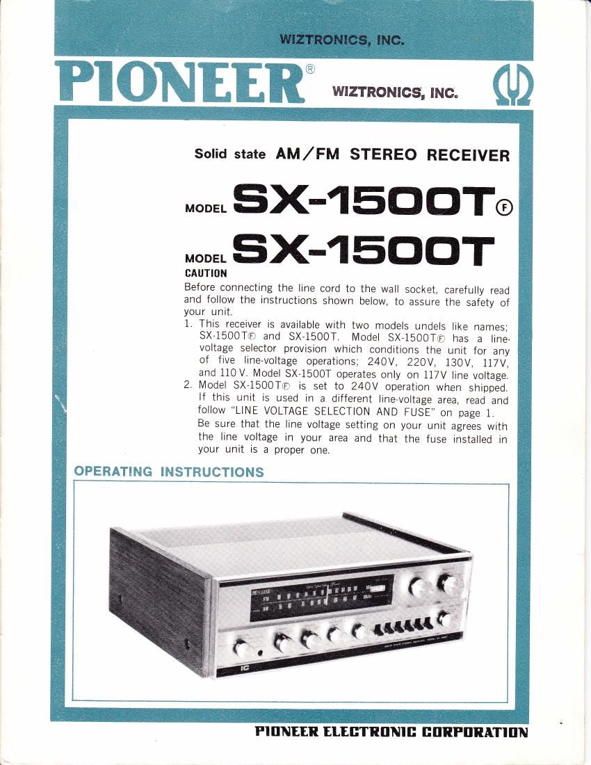
Pioneer sx 1500 t owners manual

This is the 25 pages manual for pioneer sx 1500 t owners manual.
Read or download the pdf for free. If you want to contribute, please mail your pdfs to info@audioservicemanuals.com.

Page: 1 / 25
left right
pioneer sx 1500 t owners manual

Extracted text from pioneer sx 1500 t owners manual (Ocr-read)


Page 1

TPIONEE, SOME UNIQUE FEATURES: aFM front - end employing a field effect transistor to hear more stations more clearly olntegrated circuit (lC) employed in FM tuner assures outstanding capture ratio with high reliability. oMultiplex circuitry (MPX) for maximum channel separation oUnique muting circuit permits the easiest tuning control oHigh performance single ended push-pull (SEPP) output stage eliminates audio transformers and provides large output with true frequency fidelity oFull complement of inputs and outputs By the use of FET (field effect transistor) in the FM radio frequency ampl fier stage, design of nearly perfect FM front-end was achieved-free from cross modulation, f ree f rom drift, with better sensitivity, lower inhere nt noise, and high spurious rejection ratio. ln the Fl\4 intermediate frequency amplifier stage, integrated circuits are employed, resulting in an entrely different outstanding performance from that of lFstages hitherto designed, especially in the limiter characteristic and the capture ratro. The accurate electronic switching circuitry is employed in the FM multiplex demodulator, insuring maximum separation with excellent tonal quality. The mutrng circuit provided in the FM tuner completely elim nates the FM inter-station noise which has hrtherto been annoying the user in tuning. The power amplif ier employs the hlgh-performance single ended push,pull circuitry in the output stage and the push pull complementary ctrcuitry in the driver stage, completely eliminating the distortion inherent transformers from the audio stage. Tripple diffused mesa transistors are adopted as the power transistors in the output stage for full-fidelity frequency response with large audio output power and least harmonic distortion. The inputs and outputs provided in the receiver include two pairs of pllONO MAG inputs. When two turntables are connected to these inputs, the user is able to switch from one turntable to the other any time at wrll. AIso. two pairs of loudspeaker outputs are included for switching between, or for per- mitting the simultaneous use of, two loudspeakers. The electronic switching circuitry employed in the power supply cornpletely protects expensive power transistors even when the loudspeaker leads are shorted wh le the recerver unit is in use. oElectronic switch fully precious power transistors INSTALLATION protects the Remember that the SX i500T is a transistorized receiver. Desira- ble places to install the SX-1500T are: OPlaces airy and free from humidity and on close, low-ceiling shelves. aPlaces not directly exposed to the sun aPlaces not close to heat-emitting objects stoves OPlaces where there is as little vibration as possible and where the surface is level. The optimum stereophonic listening position is across the room from the speakers, somewhere close to the midpoint between the right and left speaker systems. dust. Avoid installing ray.such as heaters and LINE VOLTAGE SEI.ECTION AND FUSE Switching Line Voltage Setting and Fuse In order to remove the fuse, turn the fuse cap located on the line voltage selector switch in the direction indicated by an arrow. Then remove the fuse plug from the unit. Put the fuse plug back so that the proper line voltage marking can be seen thru the cut on the edge of the plug. Whenever the set position of the selector switch is changed, check the rating of the fuse. A 1.5-ampere fuse is to be used for either 220Y or 240 V operation and a 3-ampere fuse for any of 110V, 117V, or 13OV operation. lf the rating of the fuse is proper, install the fuse on the fuse cap. @ SOCXET T.ko ott the tuse cap by lurninq I wilh a 6in, Erc. in the dnection andicared by the Fie 1 OReplacing of Fuse When the fuse is blown off, the fuse with a new one. remove the fuse cap and replace

Page 2