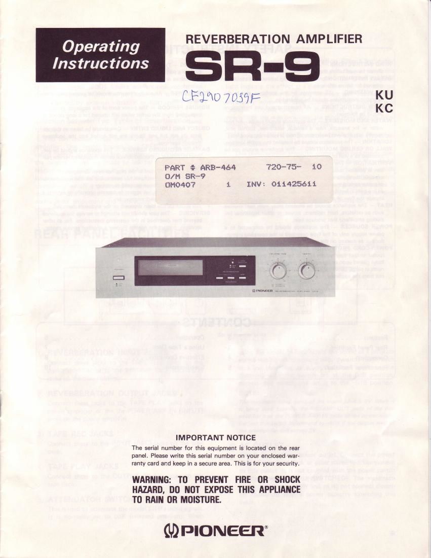
Pioneer sr 9 owners manual

This is the 10 pages manual for pioneer sr 9 owners manual.
Read or download the pdf for free. If you want to contribute, please mail your pdfs to info@audioservicemanuals.com.

Page: 1 / 10
left right
pioneer sr 9 owners manual

Extracted text from pioneer sr 9 owners manual (Ocr-read)


Page 1

SAFETY INSTRUCTIONS CONTENTS 3 3 4 5 READ INSTRUCTIONS -'All the safety and operating instiucrions should be read before the appliance is operated. RETAIN INSTRUCTIONS - The operating instructions should be retained for future reference. HEED WARNING - All warnings on rhe appliance and in the operating instructions should be adhered to. FOLLOW INSTRUCTIONS - All operating and use instructions should be followed. WATER AND MOISTURE - The appliance should not be used near water - for example. near a bathtub, washbowl, kitchen sink, laundry tub, in a wet basement, or near a swimming pool, etc. LOCATION - The appliance should be installed in a stable location. WALL OR CEILING MOUNTING - The apptiance should not be mounted to a wall or ceiling. VENTILATION - The appliance should be situated so that its loca- tion or position does not interfere with its proper ventilation. For example, the appliance should not be situated on a bed, sofa, rug, or similar surface that may block the ventilation openings; or, plac- ed in a built-in installation. such as a bookcase or cabinet that may impede the flow of air through the ventilation openiigs. HEAT.- The appliance should be situated away from heat sources such as radiators, heat registers, stoves, or other appliances (in- cluding amplifiers) that produce heat. POWER SOURCES - The appliance should be connected to a power supply only of the type described in the operating instruc- tions or as marked on the appliance. POWER-CORD PROTECTION - Power-supply cords should be routed so that they are not likely to be walked on or pinched by items placed upon or against them, paying particular attention to cords at plugs, convenience receptacles, and the point where they exit from the appliance. CLEANING - The appliance should be cleaned only with a polishing cloth or a soft dry cloth. Never clean with furniture wax, benzine, insecticides or other volatile liquids since they may corrode the cabinet. POWER LINES - An outdoor antenna should be located awav from power lines. NONUSE PERIODS - The power cord of the appliance should be unplugged from the outlet when left unused for a long period of time. OBJECT AND LIOUID ENTRY - Care should be taken so that ob- jects do not fall and liquids are not spilled into the enclosure through openings. DAMAGE REOUIRING SERVICE - The appliance should be ser- viced by Pioneer authorized service center or qualified service per- sonnel when: o The power-supply cord or the plug has been damaged; or o Objects have fallen, or liquid has been spilled into the appliance; or o The appliance has been exposed to rain; or . The appliance does not appear to operate normally or exhibits a marked change in performance; or o The appliance has been dropped; or the enclosure damaged. SERVICING - The user should not attempt to service the appliance beyond that described in the operatirig instructions. For all other servicing, contact the nearest Pioneer authorized service center. Rear Panel Facilities Operation Using a Tape Deck Effective Operation Specifications.... 6 7 8 10 Connection Front Panel Facilities Features

Page 2

FEATURES All-Electronic Reverberation Amplifier This is an all-electronic reverberation amplifier which in- corporates an audio-use delay element known as a buck- et brigade device (BBD). Unlike conventional mechanical reverberation amplifiers, this particular unit is not in the least affected by external vibration or fluctuations in the reverberation effect. Selection between Two Types of Reverberation Effect You can choose freely between two modes with this amplifier. One mode, known as EFFECT-1, is the so- called "echo" mode when the reverberation components of the original sound are made to last for a long time - a feature which is effective in large halls. The other mode, known as EFFECT-2, refers to a single reverberation component which is generated to turn a solo vocal into a chorus or duet. Make the most of these two effects to derive more enjoyment and satisfaction from your music sou rce. REAR PANEL FACILITIES Visually Attractive Reverberation Effect Indicator This indicator is designed to express the reverberations produced visually. The flickering of the green rings of light indicate the effect at a glance. When the reverberation time is long, the flickering intervals will increase, and conversely when the time is short, these intervals will decrease. Another function of the display is to display the strength of the reverberations: the more revebreration com- ponents, the brighter the rings of light. TIME and DEPTH Controls to Adjust Reverbe- ration Effect This reverberation amplifier comes with two handy con- trols: the TIME control that allows the delay time to be adjusted continuously and the DEPTH control which allows the depth of the reverbration to be adjusted con- tinuously. Using the two knobs in combination makes it easy to produce the desired reverberation effect in line with the music source which you are listening to. c REVERBERATTON INPUT JACKS Connect these jacks to the TAPE REC jacks on the stereo amplifier or to the PREAMP OUT (OUTPUT) jacks on the preamplifier. @ nevenBERATroN ourPUT JAcKs Connect these jacks to the TAPE PLAY jacks on the stereo amplifier or the the POWER AMP lN (INPUT) jacks on the power amplifier. @ rnpe REc JAcKS Connect these to the INPUT (REC) iacks on the tape deck. @ rnpe PLAY JAcKs Connect these to the OUTPUT (PLAY) jacks on the tape deck. @ nrreruuAToR swrrcH This is used to attenuate the model SR-9's inputsignals. It is normally set to OdB (released position). When using the model to reverberate the sound of a program source having an extremely wide dynamic range, such as a live recording, or when the sound appears to be distorted with the switch set at the OdB position, depress this switch and set it to the -6dB position. NOTE: The maximum rated input of the model SB-9 r's 2V. When it is being used between the PREAMP OUT jacks of the pre- amplifier and the PowER AMP lN jacks of the power ampli- fier, set this switch beforehand to -6dB if the output level of the preamplifier will exceed 2V. AC OUTLET This is an auxiliary power outlet. Connect the power plug of .your tape deck or other stereo hi-fi component to this outlet. lt is not coupled with the power switch on the model SR-9 (UNSWITCHED). The maximum power capacity is 100W and so do not connect electri- cal appliances with a power capacity exceeding this value. @ 5