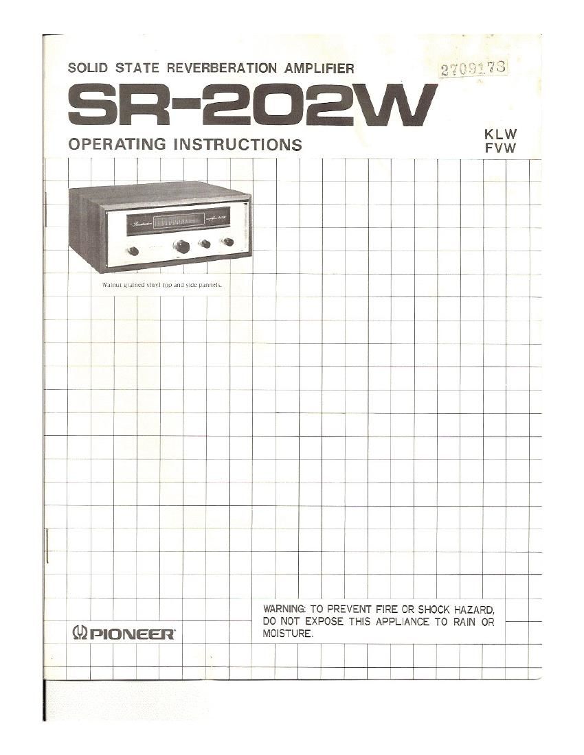
Pioneer sr 202 w owners manual

This is the 10 pages manual for pioneer sr 202 w owners manual.
Read or download the pdf for free. If you want to contribute, please mail your pdfs to info@audioservicemanuals.com.

Page: 1 / 10
left right
pioneer sr 202 w owners manual

Extracted text from pioneer sr 202 w owners manual (Ocr-read)


Page 1

r

, SOLID STATE REVERBERATION AMPLIFIER :3;?737
SR-EDEWW
KLW
OPERATING INSTRUCTIONS FVW

_, . h

3 ~77 j

l 3

. 3 3 3

I 7 ,E, 3 V 3 I _ _ ,. _
3

r
WARNING: TO PREVENT FIRE OR SHOCK HAZARD,
~ 7- ~ 7 i 3 DO NOT EXPOSE THIS APPLIANCE T0 RAIN 0R
GDPIONEER MOISTURE.
7 " | 3
I

Page 2

Thank you very much for your purchase of the solid-state REVER-
BERATION AMPLIFIER SRVZOZW.

You can enjoy reproducing any sound or recording with your favorite
REVERBERATION EFFECT through the use of the SH-202W simply
connected to your amplifier (or receiver) and tape recorder (5).

FEATURES

NATURAL REVERBERATION

Employing fully translstorized circuitry and a higheperfcrmance re-
verberation unit, Model SR-202W can add natural reverberation to
AM or FM radio broadcasts.

It can also be used for record play, and with one or two tape recorders
or tape d cks.

CONTI; IUSLY ADJUSTABLE
REVERi TION TIME

Reverberatit "9 can he adjusted as desired. An easy-to-view in-
dicator is provided.

TWO TAPE RECORDERS SIMULTANEOUSLY
CONTROLLAB LE

Two tape recorders can be controlled at the same time by switch
operation for simultaneous recording, recording with reverberation,
playback, etc.

EASY-TO-USE AND NEAT IN APPEARANCE
Model SR-ZOZW IS designed to prowde easy operation for anyone.

LINE VOLTAGE SELECTOR AND FUSE

The SR202 is available in two models: one model operates
only on 120V, and the other does on one of the five line
voltages, 110V, 120V, 130V, 220V and 240V. If your
SR-202 is the latter model, set the unit to the proper line
voltage by following the procedure described below.

SWITCHING LINE VOLTAGE SETTING AND FUSE

To remove the fuse, turn the fuse cap located on the line
voltage selector switch in the direction indicated by the
arrow.

Then remove the fuse plug from the unit. Put the fuse plug
back so that the proper line voltage marking can be seen
through the cut on the edge of the plug. Whenever the
position of the selector switch is changed> check the rating
of the fuse. A 0.2A fuse is to be used for either 220V or
240V operation and a 0.3A rating for 110V, 120V or 130V
operation. If the rating of the fuse is correct, replace cap,

FUSE REPLACEMENT
When the fuse blows, remove the fuse cap and replace the
fuse with a new one.

1

FUSE PLUG

FUSE CAP

com

Take off the fuse can by turning it with a coin in the
direction Indicated by the arrow.

Fig, 1