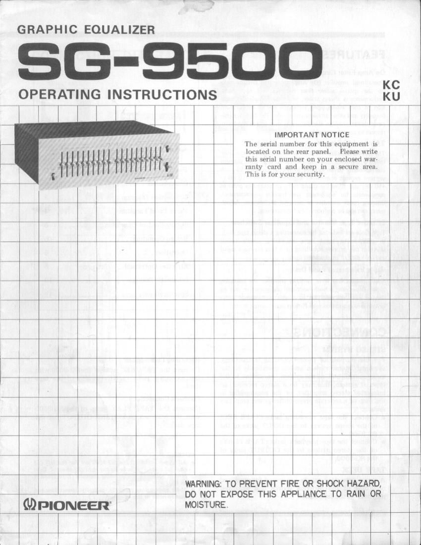
Pioneer sg 9500 owners manual

This is the 10 pages manual for pioneer sg 9500 owners manual.
Read or download the pdf for free. If you want to contribute, please mail your pdfs to info@audioservicemanuals.com.

Page: 1 / 10
left right
pioneer sg 9500 owners manual

Extracted text from pioneer sg 9500 owners manual (Ocr-read)


Page 1

GRAPHIC EQUALIZER

6-9500

OPERATING INSTRUCTIONS

KU

i r i }

IMPORTANT NOTICE

The serial number for this equipment is
Im'ulm on thr- Itlfl panel,
this serial numhvr on your i-nclosvd war-
ranty card and ktop in a secure zuvzi.
'IIm is for your security.

Phase write

,, 77L

MOISTURE.

1 i

i ,,
i Tm

I WARNING: TO PREVENT FIRE OR SHOCK HAZARD,
DO NOT EXPOSE THIS APPLIANCE TO RAIN 0R

i""i

i .|

Page 2

FEATU R ES

Op Amp Filter Circuits

Operational amplifier (Op Amp) integrated circuits make
up the special active filter networks for each band.
Pcrlormancc is always stable, while the complete climina~
lion of coils avoids aging variations due to temperature,
humidity and other ambient conditions. The high dynamic
range design provides low distortion over a wide band with
respect to any input Signal,

2 Channel 10 Element Graphic Equalizer

The graphic equalizer divides Ihe audio frequency spectrum
into 10 segments from 32 Hz to 16 kHz, each segment
corresponding to an octave. Individual controls lor each
segment provide continuous adjustment (from . 10 dB to
+10 dB) and allow the sound to be contoured in order lu
compensate for equipment and speaker characteristics,
listening room acoustics or personal preferences. Adiust-
ments can also he performed during recording.

Effective Tape Monitor and Equalizer Switches
Tape jacks are included for connecting a stereo tape deck
In addition to input signal equalizing, simple swrtch
selection can provide equalizing for a tape playback signal
and recording of an equaliled signal.

Easily Interpreted Panel Design

Slide controls and lever switches compose the operating
panel. lhe styling is both functional and attractive, making
this an excellent addition to 'a high perlormance audio
syitem in combination with Pioneer audio components,

CONTENTS

Features ......................... 2
Connections ...................... 2
Connection Diagram ................ 3
Front Panel Facilities ............... 4
Octave Control Operation ........... 5
Before Operating .................. 6
Operation ........................ 6
Effective Operation ................ 8
Schematic Diagram ................. 10
Specifications ..................... 12

CONNECTIONS

STEREO SYSTEM

For the purpose of these Operating Instructions.
the term stereo system" refers specifically to the
main control unit of the system. According to the
type of system, this may be a stereo receiver, an
integrated stereo amplifier, or the preamplifier in
the case of a separate preamplifierApower amplifier
system.

0 Connect the tape recording jacks (TAPE REC)
of the stereo system to the INPUT jacks of the
SG~9500.

0 Connect the tape playback jacks (TAPE PLAY)
of the stereo system to the OUTPUT jacks of
the 86-9500.

TAPE DECK

A stereo tape deck can be connected for equalized
recording of the program source and equalized
playback of the tape signal.

Recording Connections

Connect the TAPE REC jacks of the 80-9500 with
the recording jacks (LINE INPUT] of the tape
deck.

Playback Connections

Connect the TAPE PLAY jacks of the SG-9500
with the playback jacks (LINE OUTPUT) of the
tape deck.

NOTES-

. All upper jacks of the 809500 are for the left (L)
channel and Iowerjacks for the right (R) channel. Take
care to connect corresponding channel: (L to L and R
to R).

Make connections carefully. as faulty connections can
lead to noise or loss of sound,