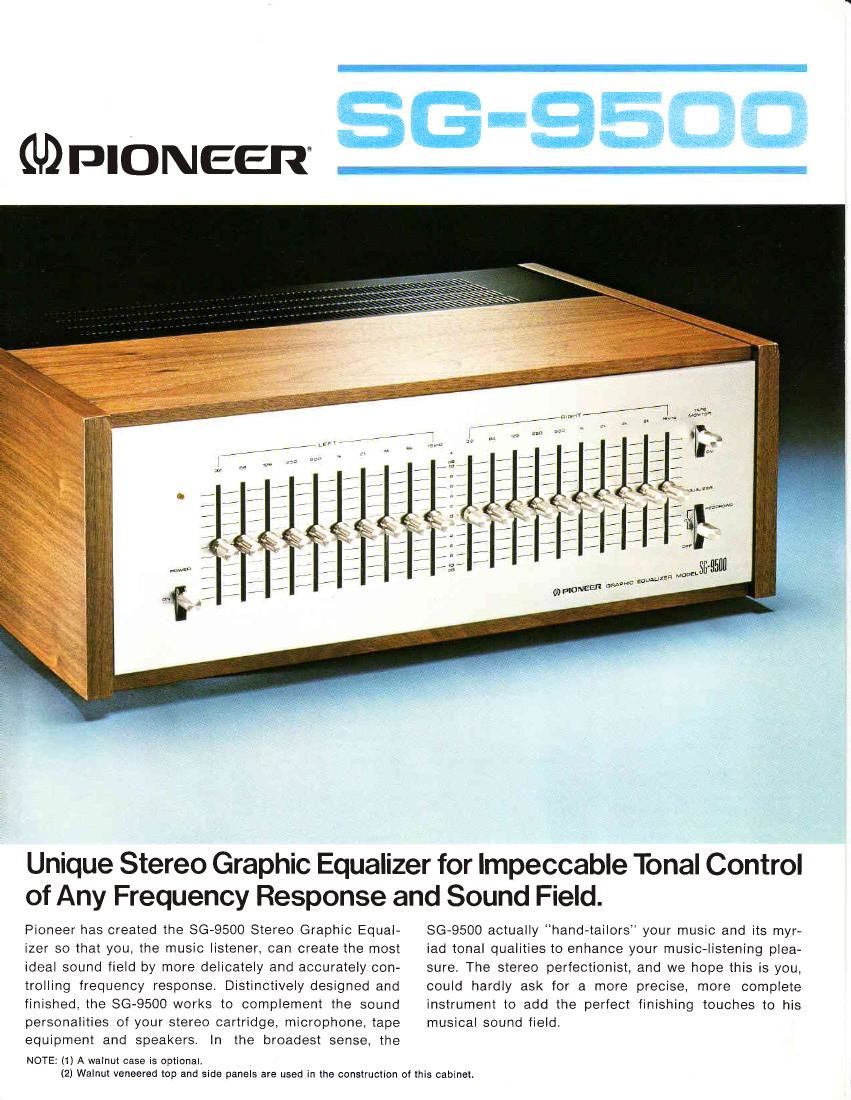
Pioneer sg 9500 brochure

This is the 2 pages manual for pioneer sg 9500 brochure.
Read or download the pdf for free. If you want to contribute, please mail your pdfs to info@audioservicemanuals.com.

Page: 1 / 2
left right
pioneer sg 9500 brochure

Extracted text from pioneer sg 9500 brochure (Ocr-read)


Page 1

sGi-95cIcl - - * -. -:"'_ :" LEVEL CONTROL WITH ONE OCTAVE CUTOFF, INDEPENDENT LEFT AND RIGHT CHANNELS The level control is cut off by one octave in 10 elements of 32H2, 64H2, 125H2, 25OHz, 500H2, 1kHz, ZkHz, 4kHz, 8kHz, and 16kHz, and the left channel (L. ch) and right channel (R. ch ) can be operated independently. The variable range of each element is +1OdB. IC OPERATION AMPLIFIER Unlike any other graphic equalizer, SG-9500 uses an Inte- grated Circuit instead of ordinary coils and capacitors. The lC contains 20 transistors and 2 diodes (x1 0 elements) and each lC operates as an active bandpass filter by negative feedback technology. This helps minimize distortion and con- tributes to expansion of dynamic range. MULTIPLE REPRODUCTION AND RECORDING TECHNIQUES By combining the TAPE MONITOR SWITCH and EQUALIZER SWITCH, six different recording and reproducing methods can be accomplished without connecting or disconnecting the cords of the SG-9500. With the EQUALIZEFT SW switched off, the EQUALIZER circuit is bypassed. Reference to the wiring diagram reproduced on the unit's rear panel as shown below, adds to the convenient reproduction and recording possibilities of the SG-9500. Equalizer Switch ON /Recording ON OFF ] =q) lrLo za IN OUT IN OUT PURE FET-EQUIPPED ELECTRONIC TYPE MUTING A pure electronic type control muting circuit is employed in the SG-9500 with an FET in the output stage in series. This eliminates pop noises when power is sr,vitched on and off. PROFESSIONAL, DISTINCTIVE DESIGN The SG-9500 is a beautifully designed instrument that will make a handsome addition to any existing stereo system. lts immaculate aluminum surface and professional knob-layout contributes to efficient operation. SG-9500 SPECIFICATIONS EOUALIZER SECTION Equalizer Range (lndividual Channel Adjust): Total Harmonic Distortion: 20Hz to 20kHz, All Control Flat Output 1V: 1kHz, All Control Max. Output 3V: 1kHz, All Control Flat Output 2V: 1kHz, All Control Min. Output 1V: lnsertion Loss: Max. Output Voltage (1 kHz, T.H.D.: 0 05%, RL 47 Kohms) Frequency Response: Signal-to-Noise Ratio +10d8, 32H2, 64H2, 1 25H2, 25OHz, 'OOHZ, 1kHz, 2kHz, 4kHz, 8kHz, 1 6kHz 0.04o/oO.O4o/o0.03%0.05%0dB (Control Flat) 6VsHz to 70kHz+0d8, -1dB (lHF, Short circuited A Network, Input Impedance: n,,tn'rt lmnodrn^o' SEMICONDUCTORS FETs:Trans isto rs: Diodes:MISCELLANEOUSPower Requirement: Power Consumption: Dimensions: Weight: 2V Output): 90dB 1 00 Kohms 600 ohms 142 1 20Vl60H2 only 16 watts Without package: 1 6-1 /2(W) x 5.7/8(H) x 1 3-711 6(D) inches 420(W) x 150(H) x 341 (D) mm Without package: 15 lb 3 0216 gkg (Drrlt)NEEFl' PICINEEFI ELECTFICINIC CGIFIIICIFIATICIN/4-1, Meguno ''l-chome, Megutro-ku, Tokyo 153, Japan U SS. FIONEEFI ELECTFIONICS COF|P /85 Oxfond Drive, Moonachie, NewJensey O7O74,lJ S A PIONEEF| ELECTFIONIC tEUFIOPEI N.V /Luithagen-Haven 9, 2O3O Antwenp, Elelgium PIONEEF ELECTF|C)NICS AUSTFIALIA PTYLTD l17e1e4 Boundany Fload, Elnaeside, Victonia 3195, Austtralra 30,000J-F-2-78 Printed in Japan