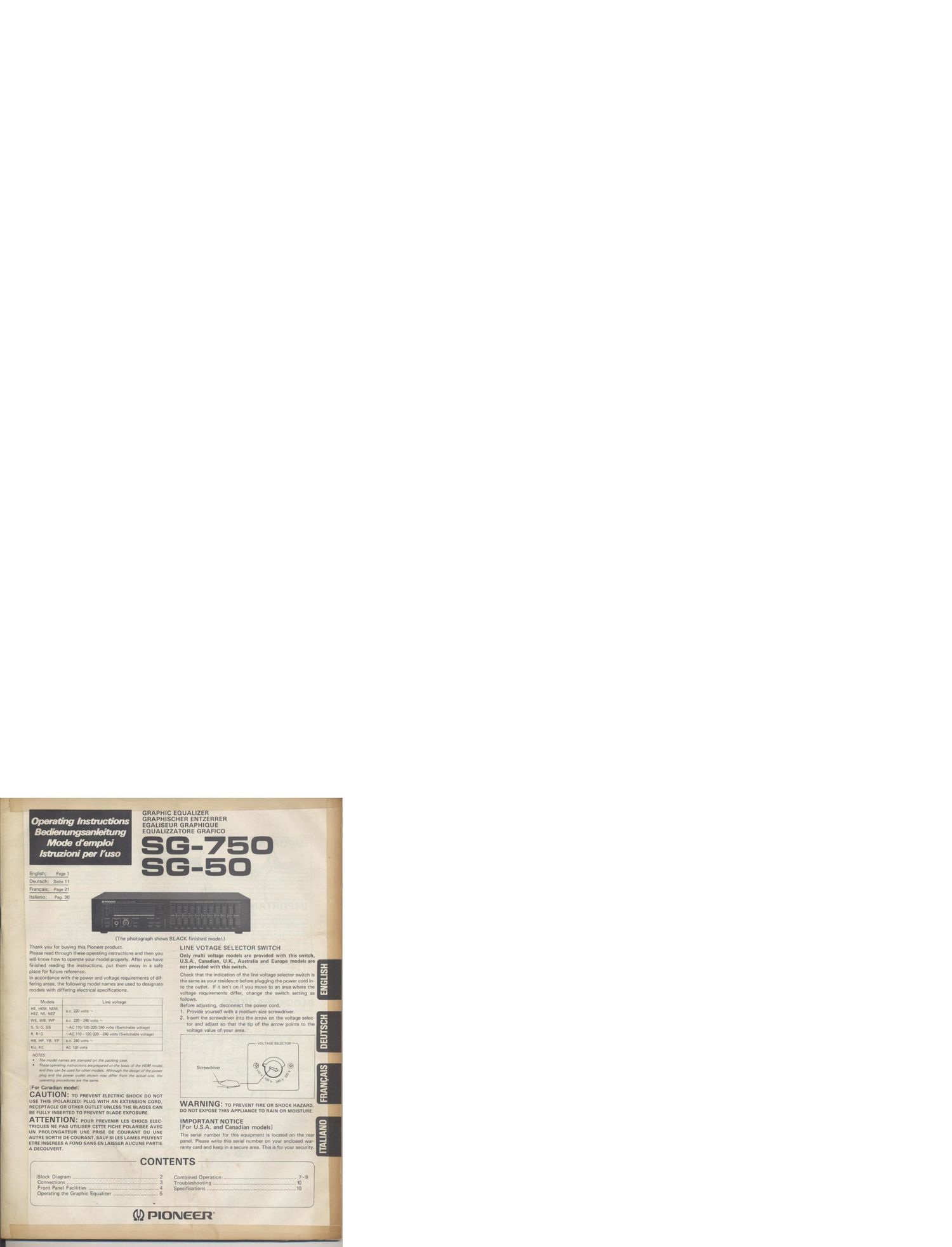
Pioneer sg 750 owners manual

This is the 10 pages manual for pioneer sg 750 owners manual.
Read or download the pdf for free. If you want to contribute, please mail your pdfs to info@audioservicemanuals.com.

Page: 1 / 10
left right
pioneer sg 750 owners manual

Extracted text from pioneer sg 750 owners manual (Ocr-read)


Page 1

ting Instructions
. rienungsanleltung
Mode demploi

istruzmni per Ius.

Peg. 30

_. -o I .

Hi cfien emzennen
.UB GRAPHIQUE

IzzATone GRAFICO

{3-75.

(The photograph shows BLACK finished model.)

Thankyou; for buying this Pioneer product.
Please read through these operating instructions and then you
will-know how to operate your model properly. After you have

finished reading the instructions, put them away in a safe .

place forfiiture reference.

In accordance with the power and voltage requirements of dif-
fering areas, the following model names are used to designate
models with differingalectricai specifications.

Models

HE. HEM, NEM,
HE. NE. NE!

we. we, we

s, 816.38.

R, RIG

HA, HP, YB. 36

ku, Kr: »
0758:

The modd names are stamped on the packing case.
Mommy Instructions arapreparad an the basis of the HEM made],

Llne voltage

I.c. 220 volts ~

, mo. 220-240 volt: ~

NAC 11Q/120/220/240 volts (Swltchable voltage)
~AG 110- 120120-240 volts (Switchable voltage)
me. 240 volts ~

AC 120 volts

- t noun Paavsmn LES cr-Iocs ELEC-
rmoues NE PAS unusen cm: FICHE POLARISEE AVEC
UN PHOLONGATEUR suns PmsE DE counAN'r ou UNE

- auras some DE counam,saur_ SI LES LAMES psuvsur
erasmssnses A FOND SANS EN LAI ER AUCUNE PARTIE

A osoouven'r. '

Block Diagram .
Connections .....
Front Panel. Facilities
Operating the Graphic Equalizer

4

',; {CONTENTS .1

LINE VOTAGE SELECTOR SWITCH

Only Irnulti voltage models are provided with this twitch,
U.S.A., Canadian, U.K., Australia and Europe models are
not provided with this switch.

Check that the indication oi the line voltage selector switch is

' the same as your residence before plugging the power cord in-

to the outlet. If it isnt on if you move to an area where the

voltage requirements differ, change the switch setting as

follows. , -

Before adjusting, disconnect the power cord.

1. Provide yourself with a medium size screwdriver.

2. Insert the screwdriver into the arrow on the voltage selec-
tor and adjust so that the tip of the arrow points to the
voltage value of your area.

VOLTAGE SELECTOR

Screwdriver

WARNING: TO PREVENT FIRE on SHOCK H

DO NOT EXPOSE THIS APPLIANCE T0 RAIN OH MOIS

IMPORTANT NOTICE

[For U.S.A. and Canadian models]

The serial number for this equipment is located on the-
panel. Please write this serial number on yourencioae'd _ _ .
ranty card and keep in a secure area. This is for your 39le P

Combined Operation
Trouhl' oting.

Brunei .
1

OHS m...

Page 2

IMPORTANT 1

The Iighming M with IWWIMG. wlthln In
mull-«ml xrianglc. In Inland-d lo m In. um of me
prance uI win-ma dunqlmu- valugt" wllhin un-
producl: lnclcnuu (ha may bun wfliclem mngnllude
lo uomtnvu 3 risk 9! mm: muck u: wanna.

CAUTION

FIQK HF ILILTIHF aHlM'K
IN/ NUT HII N

CAUTION:

TO PREVENT THE RISK OF ELECTRIC SHOCK, DO
NOT REMOVE COVER IOII BACKI. N0 USER
SERVICEABLE PARTS INSIDE, REFER SERVIC-
ING TO QUALIFIED SERVICE PERSONNEL,

The axclamulan paim within In aqudaloml munqla is
inlanm l0 ilin thc law a! mu pretence o! imporum
upswing and mumm- (Ian/Icing) instructions in
me lilmtura ucwpmylm mo wimcl.

IMPORTANT 2

II Inc upon-«m II mud wllh AC mains power oufletlll.
II. REAR PANEL FACILITIES Ia! convanism connec-
tian of mum-I HI-Fl camponumlll Mlkn all comet
don. lo 12.. AC uulktll) and (he Ilqnll mmlnlll Iim.
Comm tho plug to me wall Inckll Inn, make lure mu
m. pawn when I- a". Disccnmcl ma wall plug whun
w mlpmm In nol In lvugulu) un, up when on
vocation.

FOR USE IN THE UNITED
KINGDOM

WAHNING: TI'III plug mun only bu commend to
Ilocnonlc lap-lulu: Iqulppld wllh lull-bl-
locks.

0mm Inn on ma dllpnu u m. plug, mu m
In wamva-N on- in lcculdlncn wlth Iho lnunm-
(Ion bnlow.

Th9 wiru In VIII! mIIflt Ind an antenna In Incuvdlnm

Wllh the Iolllwlinq 003':
HIM: Mflml
31W": Liv.

As (he oolnun M m Mm hm. Mm Ind OI this Jp-
purnul may no! cavmpmd with th- oolomod marking
IdanliIvinq ma mun-II In Win DWI Dmcud u
lollows:

The wire which in colour-d um mm bu cannmw to
ma Terminal which II mldfld WIYh m. In! M or col-
ourud black.

The who which Is coloured Mwn mun b: cannon-d lo
the Iovminal which II mlrlmd Mm Ml I01!" L a cot
ourud red.

BLOCK DIAGRAM

EQUALIZER
INPUT

E SOURCE
\

TAPE


E0 switch

EQUALIZER
OUTPUT
M]

from fish. OUT

ANALYZER
IND.

Microphone