Pioneer sg 540 owners manual

This is the 29 pages manual for pioneer sg 540 owners manual.
Read or download the pdf for free. If you want to contribute, please mail your pdfs to info@audioservicemanuals.com.

Page: 1 / 29
left right
pioneer sg 540 owners manual

Extracted text from pioneer sg 540 owners manual (Ocr-read)


Page 1

OpaafimyhmmeMWm
BaflwmmmaMbmmg

AhmbcfimuMfi
bfluflmfipwdbma

Page 1

Serie i7

Francals, Page 33
Italiano, Pag. 49

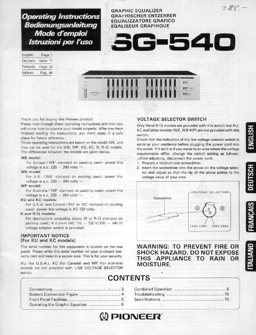
GRAPHIC EQUALIZER
GRAI'HISCHER ENTZERRER
EQUALIZZATORE GRAFICO
EGALISEUR GRAPHIOUE

56-540

i lllllliiillll

Thank you for buying this Pioneer product.

Please read through these operating instructions and then you
will know how to operate your model properly. After you have
finished reading the instructions, put them away in a safe
place for future reference.

These operating Instructions are based on the model WE, and
they can be used for the WB, WP, KU, KC, R, R/G models.
The differences between the models are given below.

WE model:
For Europe (WE stamped on packing case): power line
voltage is ac. 220 7 240 volts N.

WB model:
For U.K, (WB' stamped on packing casel: power line
voltage IS a.c, 220 . 240 volts N.

WP model:
For Australia iWP' stamped on packing case): power line
voltage is ac. 220 7 240 volts N.

KU and KC models:
For U.S.A. and Canada (KU or KC stamped on packing
case): power line voltage is AC 120 volts.

R and R/G models:
For destinations excluding above (R or RVG stamped on
packing case); A 2 point (AC 110 120 V/220 240 Vl
voltage selector switch is provided.

IMPORTANT NOTICE
[For KU and KC models]

The serial number for this equipment IS located on the rear
panel. Please write this serial number on your enclosed war»
ranty card and keep in a secure area. This is for your security.

KU lfor U.S.A.), KC (for Canadal and WP (for australia)
models are not provided with LINE VOLTAGE SELECTOR
swrtch,

Connections .....................
System Connection Figure
Front Panel Facilities ..................
Operating the Graphic Equalizer

mans-m

CONTENTS

VOLTAGE SELECTOR SWITCH

Only Ra'td R/G models are provided with this switch but KU,

KC and'other models (WE, WB WP) are not provided with this

switch.

Check that the indication of the line voltage selector switch is

same as your residence before plugging the power cord into

the outlet, If it isn't or if you move to an area where the voltage

requirements differ, change the switch setting as follows.

.efore adjusting, disconnect the power cord.

1. Prepare a medium size screwdriver.

2. Insert the screwdriver into the arrow on the voltage selec-
tor and adjust so that the tip of the arrow points to the
voltage value of your area.

VOLTAGE SELECTOR

Screwdriver
l

IlDV~120V

220V-240V

WARNING: TO PREVENT FIRE OR
SHOCK HAZARD, DO NOT EXPOSE
THIS APPLIANCE T0 RAIN 0R
MOISTURE.

n

Combined Operation .. 8
Troubleshooting ..... . 15
Specifications ........................................... 15

(L9 PIONEER

Page 2

SAFETY INSTRUCTIONS [FOR KU MODEL]

READ INSTRUCTIONS 7 All rhe sarery and
uperalmg .narrucudns should be read berore the
appllance ls operaled

RETAIN :NSTnucrlons The operatlng msuuc
hens should be retained ror Iutum ralaranee

NEED WARNING 7 All warnlngs on the apphance
and In tho operatlng lnstrucllons should be adhered
to

FOLLOW INSTRUCTIONS 7 All operanng and use
lnstructlons should be Iollewed.

WATER AND MOISTURE 7 The apollanca should
not be used near warar tar oxampla. near a
bathtub, washbowl, Itltchen slnk, laundry tub. In a
wut basement, or near a awummlng pool, ere

LOCATION The appllance should be Installed In a
stable IDCaIlOn

WALL on CEILING MOUNTING 7 rhe applrance
should not he mountttd to a wall or aollrng

VEN'nLATION , The appllance should be owned so
rhal Its lecanon or poamon does not lnlerlera wIIh
lu proper venlllatran For example, rho appllance
should not be sheared an a bed, sera, rug, or
srmlllr surtaoe rhal may block rho vanlilatlon open
lnps, or, placed in a [null ln lnatillali n, such as a
bookcase ar cabmot that may impede the Ilow ov
air through me uanIIIaI-on openrngs

NEAT 7 The appliance should be sltuated away lrern
heal sources such as radlarors, hear reglsrers,
stoves. or other apnllances (Includlng arnplrhersl
that produce hear

POWER SOURCES 7 The appllanca should be con
necled lo a power supply onry or the type dascno
ed in «he Operatmg rnsrrucuons or as marked on The
appliance

POWERconn PROTECTION 7 Power supply cords
should be routed so Ihal rhey are not lrtely to be
walked on or plnchod by Items placed upon or
agnrnal rharn, paymg pamcular attention ro cords
ar plugs, Convenience recepraclee, and the palm
where rhey em Irem lhe appllance

CLEANING 7 The aopllnncs should be cleaned only
wnh a pullshlng Cloth or a son dry cloth Never
clean with IuInlturu wall benzrne, lnsecllcldes or
other volatlle llqulds slnce lhey may corrode rho
camrlat.

POWER LINES 7 An outdoor amonna should be
loeorad away horn power lrnes

NONUSE PERIODS 7 The power cord or rhe ap
pllance should be unplugged lrern rhe ouuer when
Ieh unused Ior a long penod or lune

OBJECT ANO LIOulO ENTRV Care should be
taken so that oblocls do not tell and llqurds are nor
spllled Into the enclosure rhrough opernngs

DAMAGE REQUIRING SERVICE 7 The appliance
should he sew-cod by Ploneel authorlzed sErvlca
cenlel or qualllled smvlce personnel when

- The pwsr supply cord or rhe plug has been
damaged; or

- Obrecrs have lellen, ol Ilquld has been spllled lnro
rhe appllance; or

- The appllance has been exposed ro ram, or

I The appllance does l'lfil appear to Opelale normally
or exhrblts a markad chsnge m perlorrnance, or

- The applrance has been dropped, or Ihe enclosure
damaged

SERVICING 7 The user should not alIEmpI ID semce
the apvllance beyond mar dascnbed I" ma
operatlrlg rmrrucuons, For all other ServtCIng, con
tact the nearesr Planner authorlzed seryrca center

ourpoon ANTENNA GROUNDING 7 ll an oursrde
anrenna IS summed to the anrenna Ierrnrnal, be
sure the antenna system Is grounded so as to pro
yrde some prorecuon agamsl voltage surges and
[mill up static charges
In the u s A secuon all) or the Nauonal Electrical
Code, ANSI/NEPA No 704951, plovldoslrllorrrta
tlon wlth rupuct Io proper groundlg or the mast
and supponrng srnlclure, groundrng ol the lead In
WIra to an anrenna drseharga unh, sue oI graun
dlnp conductors, Iocsnen er anrenna dlscharge
unlt. cennaenon l0 groundrng electrodas, and re
qulrements lol the glaundlng Electrode See Flg
A

EXAMPLE OF ANTENNA GROUNDING AS
PER NATIONAL ELECTRICAL CODE INSTRUC
TIONS


Ground Clamo

ill m
Masr
ground Cr
wrre Antenna rt: Altt'llla lull-ll'hal
drscharge . .
unn
a In
Ground
Wlw
[,rourrd clarrpa
oroundrng elemrode
1nan a mo rhe earrh
r2 M metersl
Flg A

al Use No IOAWG l5 3mm copper or No 3Awo
(84 mml nlummum Or No l7 Am; (I u mml
copperrclad creel or bronze wlre. or larger as
ground wires Ier bath masl and ludrln

bl Secure Ieadun wue Irern anranna to antenna
drscherge unrt and mast ground wrre to house wnh
srend on Insulatori. spaced ham 4 leer ll 22
rnelersl re 6 leer ll .33 meters) apart

cl Mounr anranna discharge unrr as closely as pass.
ble to whore lead7rn enters house

IMPORTANT [FOR KU MODEL]
CAUTION

The lightning 'llash with arrowhead,
within an equilateral triangle, is intended
to alert the user at the presence of
uninsulated dangerous voltage" within
the products enclosure that may be of
sufficient magnitude to constitute a risk
of electric Shock to persons.

RISK OF ELECTRIC SHOCK
DO NOT OPEN

CAUTION:

TO PREVENT THE RISK OF ELECTRIC SHOCK. DO
NOT REMOVE COVER IDR RACK). N0 USER-
SERVICEABLE PARTS INSIDE. REFER SERVICING
T0 flUAUHEII SERVICE PERSONNEL

The exclamation point within an
equilateral triangle is intended to alert the
user of the presence of important
operating and maintenance [servicing] ins
structions in the literature accompanying
the appliance,

IMPORTANT

To prevent electrlc shock, do not remove cover, No user ser-
viceable parts inside; refer servicing to qualified service personnel.
It the apparatus is fitted with AC main power outletls), see REAR
PANEL FACILITIES for convenient connection of additlonal HI'FI

componentls).

Make all connections to the AC outletlsl and the signal terminals

plugt

following code:

first, Connect the plug to Ihe wall socket last; make sure that the

power switch is off.

Disconnect the wall plug when the equipment is not In regular use,

e.g. when on vacation.

FOR USE IN UNITED KINGDOM AND

AUSTRALIA

CAUTION 240 V:

FOR USE IN UNITED KINGDOM

Equipment sold in the UK. is not supplied with a power
The wires ln this mains lead are coloured in accordance With the

Blue: Neutral
Brown: Live

AS the colours of the WIres In the mains lead ol thls apparatus may

not correspond with the coloured markings Identllylng the ter»

minals in your plug, proceed as follows:

The wire which is coloured blue must be connected to the termlnal
which Is marked with the letter N or coloured black.

The wire whlch ls coloured brown must be connected to the ter
minal whlch Is marked Wlth the letrer L or coloured red.

Mains supply voltage is factory

adjusted at 240 V.

J