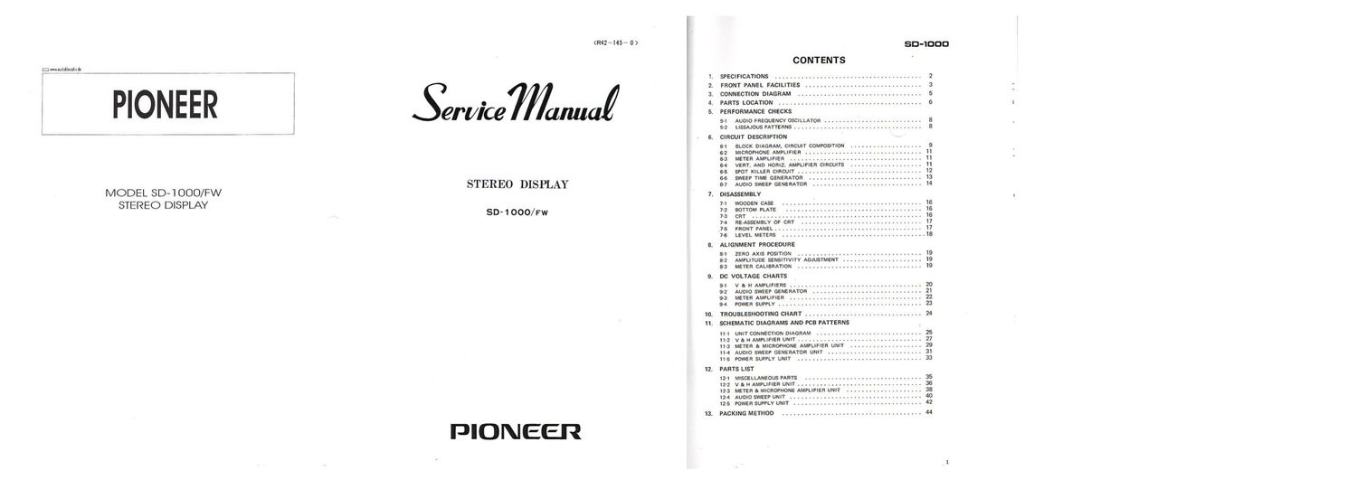
Pioneer sd 1000 service manual

This is the 13 pages manual for pioneer sd 1000 service manual.
Read or download the pdf for free. If you want to contribute, please mail your pdfs to info@audioservicemanuals.com.

Page: 1 / 13
left right
pioneer sd 1000 service manual

Extracted text from pioneer sd 1000 service manual (Ocr-read)


Page 1

(R42 *145 - 0 ) SD_°°O
CONTENTS

SPECIFICATIONS ....................................... 2
FRONT PANEL FACILITIES ............................... 3

S w audiuklassiks dz

F77 7" 7" -' I

01¢wa

. CONNECTION DIAGRAM ................................. 5
I
O . PARTS LOCATION ...................................... 6
I erylce an . PERFORMANCE CHECKS
, 5-1 AUDIO FREOUENCY OSCILLATOR .......................... 8
,7 , j 5-2 LIssAJOUS PATTERNS .................................. 8
- G. CIRCUIT DESCRIPTION
s-I BLOCK DIAGRAM. CIRCUIT COMPOSITION ................... 9
6-2 MICROPHONE AMPLIFIER ............................... 11
5-3 METER AMPLIFIER ................................... 11
6-4 VERT. AND HORIz. AMPLIFIER CIRCUITS ................... 11
65 SPOT KILLER CIRCUIT ................................. 12
6-6 SWEEP TIME GENERATOR .............................. 13
MODEL SD 1 OOO/FW STEREO DISPLAY 6] AUDIO SWEEP GENERATOR ............................. 14
7. DISASSEMBLY
STEREO DISPLAY 7.1 wooom use ..................................... 16
SD- 1 7-2 BOTTOM PLATE .................................... 16
GOO/PW 73 CRT ............................................. 16
7-4 RE-ASSEMELY OF CRT ................................ 17
77-5 FRONT PANEL ....................................... 17
7-6 LEVEL METERS ...................................... 18
8. ALIGNMENT PROCEDURE
8-1 ZERO AXIS POSITION ................................. 19
8-2 AMPLITUDE SENSITIVITY ADJUSTMENT ..................... 19
8-3 METER CALIBRATION ................................. 19
9. DC VOLTAGE CHARTS
9-1 v a H AMPLIFIERS ................................... 20
9-2 AUDIO SWEEP GENERATOR ............................. 21
9-3 METER AMPLIFIER ................................... 22.
9-4 POWER SUPPLY ...................................... 23
10. TROUBLESHOOTING CHART ............................... 24
11. SCHEMATIC DIAGRAMS AND PCB PATTERNS
-1 UNIT CONNECTION DIAGRAM ............................ 25
11-2 v a H AMPLIFIER UNIT ................................. 27
11-3 METER a. MICROPHONE AMPLIFIER UNIT ................... 29
114 AUDIO SWEEP GENERATOR UNIT ......................... 31
11-5 POWER SUPPLY UNIT ................................. 33
12. PARTS LIST
Iz-I MISCELLANEOUS PARTS ............................... 35
12-2 v a. H AMPLIFIER UNIT ................................. 36
12-3 METER & MICROPHONE AMPLIFIER UNIT .................... 38
I2-4 AUDIO SWEEP UNIT ................................... 40
I2-5 POWER SUPPLY UNIT .................................. 42
13. PACKING METHOD ..................................... 44

PIONEER

Page 2

1 . SPECIFICATIONS

SEMICON DUCTORS

Cathodeeey tube
OSCILLOSCOPE SECTION

Vertical amplifier

Horizontal amplifier

Sweep frequency range
Synchronous circuit

Additional circuit

F ETs ................ 9
Transistors ............ 40
Diodes ............ . 33

3-inch I75rnml Electrostatic-deflection type

Deflection sensitivity: 20mV p-plcm

Frequency response: 5H! - 25mm: (within ~3d8l
Input impedance: lSlOkQ

Input capacitance: SOpF

Deflection sensitivity: 20rnv p-plcm

Frequency response: 5H1 - 250kHz Iwithin -3dBI
Input impedance: ISOkQ

Input capacitance: BOpF

4 ranges IOHz- IOORHI
Synchronous level: More than 3/8 on scope
Synchronize system: Internal

"Spot killer" circuit

AUDIO OSCILLATOR SECTION

Frequency range
Output level
Output stabiIitv
Output impedance
Distortion

Sweep time:

20H: - 20kI-Iz Automatic weep, manual sweep 11096 or less
2V or_ more. variable continuously

20H: - 20kI-lz. lips or lea

4.7k9 or less

1% or less (at 20Hz-20ltl'lz)

25 seconds (from 20H: to 20km)

LEVEL METE RS SECTION

Relerence level
Input sensitivity
Response time
Frequency response

OdB - 2V lFronti, one - 20V (Rear)
oae, -10dB. -20dB

0.3 second lot to can indicate lat lkHzI
20Hz- ZOIIHl. lids

INPUT & OUTPUT TERMINALS

Front panel Inputs

Rear penel inputs

Front panel output

INPUT 1 WERT). INPUT 2 IHORIZI

Sensitivity: 20mV p-p/cm IIQOkQI

MIC (mono): Sensitivity, 0.8mV rmelcrn
Impedance. 5&9 IlkHzI

INPUT 1. 2. 3 end 4

Sensitivity: 200mV p-plcm IISOKQ)

FM MULTIPATH/VERT

FM MULTIPATH/HORIZ

Sensitivity: 20mV pp/crn

AF OSC OUTPUT 2V or more

POWER SUPPLY SECTION

Power requirements and frequency

Power commotion
Dimensions

We Ight
Accessories

NOTE: Specifications and the design subject to possible modification due to improvements.

110V. 120V. I30V, 220V and 240V. 50 - GOHI
25W (MAXI

1&15/16IWI 2 5411/1601) x l3~I1I16IDI in.
[4300) x 145IHI x 348(0) mm]

9") 602 (8.8kgl

Operating instructions ...... I
Cards with pin plug ....... 1
Polishing cloth ...... . . . . l

2. FRONT PANEL FACILITIES

CATHODE-RAY TUBE ICRTI SCREEN:
All patterns. waveforms or displays appear on this
screen. The signal level can be read on the vertical
sale in the center.

VERTICAL POSITION:
Turning the knob clodtwiea moves the pattern on the
screen upward; turning the knob counterclockwise
moves the pattern downward.

HORIZONTAL POSITION:
Turning the knob clockwise moves the pattern on the
screen to the right; turning the knob counterclockwise
moves the pattern to the left.

._ LEVEL METERS:

Direct reading or input level in decibel units. If the
input signal to be manned is applied through the
AUDIO INPUTS on the rear panel. add 2MB to the
reading on the scale

WAVEFORM & DISPLAY SELECTOR
SWITCHES (VERT):

Switch nuwbers I to 4 correspond to the Input
terminal numbers.

INPUTS 1 IVERTI:

High-sendtivity inputs for vertical amplifier; theta
terminals are used when observing a low-level input
signal. The upper is for the positive It). the lower is
let the negative I-I pole lgroundl.

INPUTS 2 IHORIZ):
High-sensitivity inputs for horizontal amplifier. other
functions are the same as for INPUT 1.

FRONT-REAR SELECTOR:
This push-button switch is set to FRONT when the
INPUTS I or 2 are usd; to REAR when the AUDIO
INPUTS on the reer panel we used. II this switch is
onto-sea. it is locked and set to REAR. and depressed
once again, it is released and saute FRONT.

VERTICAL GAIN:

Turning this knob clockwise allows vertical amplitude
of the waveform on the screen to increase.

'- SWEEP RANGE AND FREQUENCY

VARIABLE CONTROLS:

The right selector swrch chooses the sweep frequency
range. the left contra! adjusts the sweep frequency
within the prmlectid range.

The eaIeCIed sweep f-equency should be the same as
or below the signal Irrquency to be observed. Identinl
map and signal lVERT input) Iroquancies mean
that one cycle \vi be displayed on the CRT.
Lower m freoumcies let you display sveral

VERT input cycles.
The controls are only operative when the FUNCTION

SWITCH is set to \MVEFORM position.

HORIZONTAL GAIN:
Turning this knob clockwin allows horizontal

amplitude of the walefortn on the screen to increaa.

3 .

SD-IODD

DISPLAY SWITCHES IHOR IZ):

Switch numbers I to 4 correspond to the input
terminal nurrbars. To observe a Lissajous pattern on
the screen_ the switch corresponding to the input
terminals used should be depressed.

OSCI L LATOR OUTPUTS:

Them are output terminals for the built-in audio
millator. The upper terminal is for the positive (e).
the lower terminal is for the negative l-I pole
(ground).

OSCILLATOR FREQUENCY CONTROL:

Frequencies in the range from 20Hz to 20kHz can be
obtained by means of this control knob.

With the knob E! to SWEEP AUTO. the oscillator will
continuously sweep frequencies from 20H: to 20kHz
automaticelly at approx. 26 seconds for one sweep
cycle.

OSCILLATOR LEVEL CONTROL:

Turning this knob clockwise increases output or the
oscillator. With this knob set to OFF, the oscillator
stops operating. Be sure to keep the knob set to OFF
when the oscillator is not in use.

MIC JACK:

Waveform ol the sound plated up by a microphone
can be observed by planning I dynamic microphone
into this JACK. At the time. the LEVEL METER
IVERTI will show the sound level. Be sure to
disconnect the microphone when it is not used.

FUNCTION SWITCH:

POWER OFF ------- Turns power 0".

WAVEFORM For obnrvingwweforms olaignals
selected with the WAVEFORM
e DISPLAY SE LECTOH
SWITCHES.

DISPLAY ------------- For observing a Lissaious pattern
selecwd with the WAVEFOFIM at
DISPLAY SELECTOR SWITCH
and the DISPLAY SWITCH.

FM MULTIPATHm For observing multipath con
ditions of an FM antenna.

LEVEL METER SELECTOR SWITCH:

OFF The LEVEL METERS will not function.
0 - - When a signal ol 2VIrmsl is applied to
the INPUTS "I" or "2". the LEVEL

METERIS) will indicate ads.

--10 When a signal oI 0.63V l-lOdB below
2!) is applied to the INPUTS "I" or
32". the LEVEL METEHISI will indicate

68.

~ When a signal at 0.2V (-2068 below
2Vl is applied to the INPUTS "I" or
"2". the LEVEL METERIS) will indicate
OdB.