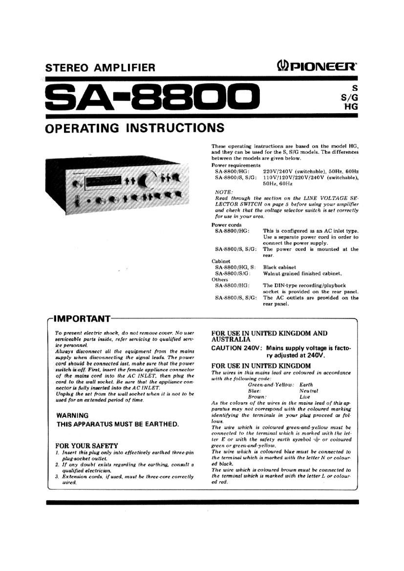
Pioneer SA 8800 Owners Manual

This is the 16 pages manual for Pioneer SA 8800 Owners Manual.
Read or download the pdf for free. If you want to contribute, please mail your pdfs to info@audioservicemanuals.com.

Page: 1 / 16
left right
Pioneer SA 8800 Owners Manual

Extracted text from Pioneer SA 8800 Owners Manual (Ocr-read)


Page 1

STEREO AMPLIFIER GDPIONEER

A-BBDD 8/
FIG

OPERATING INSTRUCTIONS

These operating imlrucliuns are based on thr- model HG.
Ind they can be um! for the S. SIG models. The difference:
between lhe models are given below.
Power requirements
SA-étSOO/IIG: NOV/240V (switchable). 50m, 60I|z
SA-fiflflms. SIG IIOVJI20VF220V12AIOV (switchable).
Sflliz, 60H:

DID

NOTE:

Read lhmugh lhe reclirm (in the LINE VOLTAGE SF."
LECTOR SWITCH on page 5 before using your amplifier
and check that the voltage selector switch is re! correctly
for use in your area

Power cord:

SA-BHOOIHG: This is configured in an AC inlet typoi
Use a reparate power cord in order to
connect the power xupplyr

SA'SSOOIS. SJG' The power cord in mounted II the

PEII.
Cabinet
SA-SaofliHG, S: Black cabinet
SA~8800iSle Walnut grained Iinishi-d cabinctr
Others
SA-SSOOMG: The DIN-typo recording/playbncli

socket is provided an the rear panel.
Six-8800,45. SIG: The AC outlets are provided on the
rear paneli

r-I M PORTANT 1
To prevent electric rtmck, do not remnue raven No user FOR USE IN UNITED KINGDOM AND

umiceable purl. inlide. refer rewiring to qualified ten» AUSTRALIA

ice penonnel. . . , .
Alwoyr diuonnect all the equipment from the main: CAUTION 240V. Mam! SUPPIY voltage I he)
rupply when disconnecting the line! lead: The power 'V Odlllfled at 240V.

card should be connected lart. make am that the pawn FOR USE IN UNITED KINGDOM

27.121l;1££f£;'::: It": [Afzflt'zgelfmtllfglnclejctiz The wine: in thin maim lead an enluured in «cranium?
card to the wall locket Be cure that the appliance can in: H" followénriecxzi Yellow Earth
nectar in IIilly inserted into theAC INLET Blue Neutral
Unplug the ul ham the wall soc-he! when it It not to be . .
Brown Liue

N" [or an 1"de period of "m" A: the coloun a] the wires in the main: lead of Hit: up
pamlus may nut corrupond with the coloured marking

WARN|NG identifying the terminal: in your plug pmceed in fal~
Iowa.

THIS APPARATUS MUST BE EARTHED' The wire which i: eolnured green-and-yellow mull be
wnnecled to the terminal which is marked with Ihr trl~
Mr E m wilh the safety earth rymbol 4- or coloured

FOR YOUR SAFETY Iran or :rcen-and-yellnw
Ii Intert this plug only into effectively (111(th 0""er Thr wire which ll coloured blue mun br connected to
pIu'JOlkCl outlet, the terminal which is marked with the letter N or entour-
2, If any :10th girls regarding the carthing, could! a N1 06
qualified zlechiciam The wire which in caloured brown mun be connected to
J, Extenn'an cordl. iliued. MUII be threecore correctly the terminal which in marked with the letter I. or colour
wired ed red.

Page 2

Featurea ...... . ............. 2
Stereo System Composition ......... . . . 3
Installation Precautions . . . 3
Rear Panel Facilities . . . . . 4
Connections ..... . . . . . 5
Front Panel Facilities . ............... . 8
Operations ...... ........ ...11

CONTENTS

EffectiveOpet-tiona .......... . . 12
UsingtheT-peDeCh................. 18
Using PRE OUT and POWER AMP IN

Jacka........... ........ ........14
Conditions Frequently Mistaken for

Malfunctions.. ...... .............15
Specifications ......... . ............. 16
Schematic Diagram .............. Insertion

FEATU RES

Power Amplifier with Ultra-wide-frequency-bartd
Output and Low Distortion

This amplifier has the impressive feature which is the
NSA (Non-Switching-Amplifier). created specially by
Pioneer. This is a type of amplifier that adopts the merits of
both the class A and class B amplifiers, and it excels in
keeping down the heat loss and allows the transistors to
operate all the time in the active region. For this reason, a
high output power with a very low distortion factor is
yielded all the way up to the high frequencies.

Also it is designed to pack a punch at every stage - this
is evident in the first stage differential input, current mirror
load; the predriver stage emitter follower drive, constant-
current load; and the outpUt stage 2'stage Darlington,
parallel push-pull output circuit configuration. All this adds
up to a DC amp configuration which uses SL RETs [Super
Linear Ring Emitter Transistors), which have an excellent
switching response in the high frequency range, for the
power transistors.

Continuous Power Output is 80watts' per chan-
nel, min.. at 8 ohms or 4 ohms from 10 Hertz to
20,000Hortz with no more than 0.005% total

harmonic distortion.

T-shaped skyve heat sink is used because it is
lightweight and it dissipates the heat very effectively.
Even when the amplifier is operating continuously under
full power conditions, these heat sinks keep the rise in tem-
perature down, and they ensure that a high-quality power is
provided.

Flat Amplifier with High S/N Ratio and Low
Distortion

This model adopts an ICL DC amplifier which is com-
posed of a twostage differential amplifier for the first stage
using ultra-low-noise dual FETs and an emitter follower for
the final stage. This construction is successful in achieving a
low distortion and a high signal-to noise ratio, and in main-
taining an SIN ratio of l lOdB (AUX).

Load Impedance Selector Switches

This amplifier comes with cartridge load selectors which
make it possible to display the performance of moving
magnet (MM) cartridges to the full for sophistication in
operation. The load resistance selector has five settings
(l00/l0k/25k/50k/100k ohms), and the load capacitance
selector similarly has five settinp [l00f200/300I400ISOO
pF) so that the two selectors can be used independently,
They allow you to make settings which are in line with the
optimum values of the phono cartridge you are using and
also to create the sound quality of your choice.

Equalizer Amplifier for Faithful Reproduction of
Sound from Records

The equalizer amplifier is composed of a complementary
differential input which uses ultra-low-noise transistors for
the first stage, and a 3-stage direct~coupled all-stage push-
pull configuration. This results in yielding a low noise and
low distortion, a signaleto-noise ratio of 90dB (PHONO
MM) and an RlAA equalization of only 20.2dB across a
frequency spectrum of 20Hz to 20kHz. The maximum
rated input is 'ZSOmV (at lkHz, 0.002% total harmonic
distortion), proving that there is more than enough head-
room for the reproduction of sound from records.

Power Output Indication on Fluorescent Display
Tubes

The conventional needle-type of power output meters
have been replaced with the more up-todate fluorescent
display tubes featuring digital technology. They employ
logarithmic compression circuits and a peak hold circuit to
indicate the power output over a 0.3mW to 80W range
without any assisting selection on the attractive fluorescent
display tubes.

2 Meoaured purulent to the Federal Trade Commie-tan} Trade Rewlation rule on Power Output Claim. for Ampllflln.