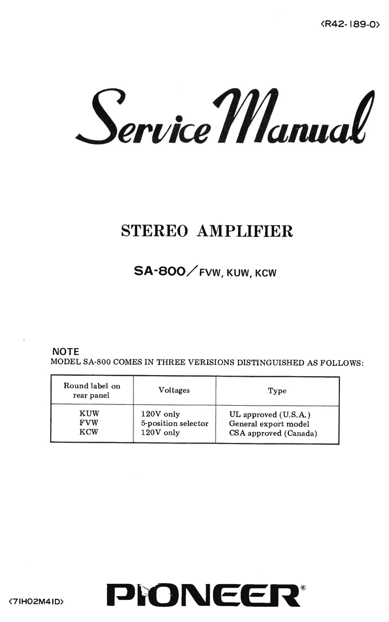
Pioneer SA 800 Service Manual

This is the 37 pages manual for Pioneer SA 800 Service Manual.
Read or download the pdf for free. If you want to contribute, please mail your pdfs to info@audioservicemanuals.com.

Page: 1 / 37
left right
Pioneer SA 800 Service Manual

Extracted text from Pioneer SA 800 Service Manual (Ocr-read)


Page 1

Sen/ice mutiny

STEREO AMPLIFIER

SA-BOO/Fvw, KUW, ch

NOTE
MODEL SA-8OO COMES IN THREE VERISIONS DISTINGUISHED AS FOLLOWS:

Round label on

Voltages Type
rear panel

KUW 120V only UL approved (U.S.A.)
FVW 5-position selector General export model
KCW 120V only CSA approved (Canada)

PFONEEJT

Page 2

SA-BDD

CONTENTS
1. SPECIFICATIONS .................................................... 1
2. FRONT PANEL FACILITIES ...................................... .. . 3
3. CONNECTION DIAGRAM ............................................. 5
4. CIRCUIT DESCRIPTION
4-1 Block diagram ....................................................... 7
4.2 Low level input circuits ................................................ 9
4-3 Head am plifier circuit .................................................. 9
4-4 High level inputs and control circuits ...................................... 9
4-5 Control amplifier circuit ................................................ 9
46 Filter ................ . .............................................. 9
47 Power amplifier circuit ................................................. 9
48 Protector circuit ...................................................... 9
49 Power supply circuit ................................................... 9
5. DISASSEMBLY '
5-1 Wooden case ......................................................... 10
5-2 Front panel ......................................................... 10
5-3 Bottom plate ........................................................ 10
5 4 Parts and PCB locations ................................................ 11
6. ALIGNMENT PROCEDURES
6-1 DC neutral voltage & detector circuit adjustment ............................. 12
6 2 Idle current adjustment ................................................ 12
7. SCHEMATIC DIAGRAMS AND PCB PATTERNS ....................... 13
8. PARTS LIST .......................................................... 22
9. PACKING METHOD AND PARTS .................. ' ................... 35