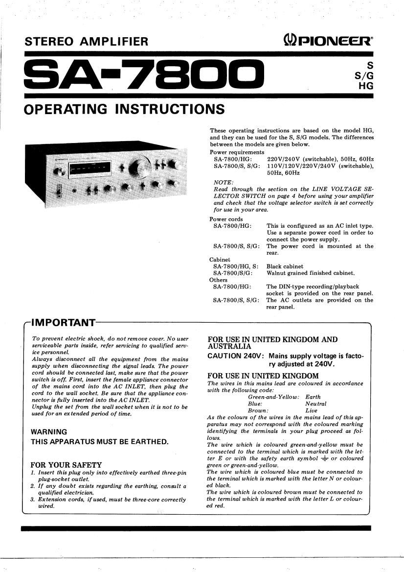
Pioneer SA 7800 Owners Manual

This is the 12 pages manual for Pioneer SA 7800 Owners Manual.
Read or download the pdf for free. If you want to contribute, please mail your pdfs to info@audioservicemanuals.com.

Page: 1 / 12
left right
Pioneer SA 7800 Owners Manual

Extracted text from Pioneer SA 7800 Owners Manual (Ocr-read)


Page 1

STEREO AMPLIFIER

QDPIONEEIT

A-7BDD ,

OPERATING INSTRUCTIONS

These operating instructions are based on the model HG,
and they can be used for the S, 8/0 models. The differences
between the models are given below.
Power requirements
SA-7800/HG: 220V/240V (switchable), 50Hz, 60Hz
SA~7800/S, S/G: 110V/120V/220V/24OV (switchable),
50Hz, (3on

NOTE:

Read through the section on the LINE VOLTAGE SE~
LECTOR SWITCH on page 4 before using your amplifier
and check that the voltage selector switch is set correctly
for use in your area.

Power cords
SA-7800/HG: This is configured as an AC inlet type.

Use a separate power cord in order to

connect the power supply.

SA»7800/S, S/G: The power cord is mounted at the
rear.

Cabinet
SA-7800/HG, S:
SA-7800/S/G:

Others
SA-7800/HG:

Black cabinet
Walnut grained finished cabinet.

The DIN-type recording/playback
socket is provided on the rear panel.
SA-7800/S, S/G: The AC outlets are provided on the
rear panel.

(IMPORTANT

To prevent electric shock, do not remove cover. No user
serviceable parts inside, refer servicing to qualified serv-
ice personnel.

Always disconnect all the equipment from the mains
supply when disconnecting the signal leads The power
card should be connected last, make sure that the power
switch is off. First, insert the female applianceconnector
of the mains cord into the AC INLET, then plug the
cord to the wall socket. Be sure that the appliance con~
nector is fully inserted into theAC INLET.

Unplug the set from the wall socket when it is not to be
used for an extended period of time.

WARNING
THIS APPARATUS MUST BE EARTHED.

FOR YOUR SAFETY

1. Insert this plug only into effectively earthed three-pin
plug

2. If any doubt exists regarding the earthing, consult a
qualified electrician,

3. Extension cords, if used, must be three-core correctly
wired.

FOR USE IN UNITED KINGDOM AND
AUSTRALIA

CAUTION 240V: Mains supply voltage is facto-
ry adjusted at 240V.

FOR USE IN UNITED KINGDOM
The wires in this mains lead are coloured in accordance
with the following code:

Green-and-Yellow: Earth

Blue: Neutral

Brown: Live
As the colours of the wires in the mains lead of this ap-
paratus may not correspond with the coloured marking
identifying the terminals in your plug proceed as fol-
lows. .
The wire which is coloured green-and-yellow must be
connected to the terminal which is marked with the let-
ter E or with the safety earth symbol -4- or coloured
green or green-and-yellow.
The wire which is coloured blue must be connected to
the terminal which is marked with the letterN or colour
ed black.
The wire which is coloured brown must be connected to
the terminal which is marked with the letter L or colourv
ed red.

Page 2

Features ........................... 2
Stereo System Composition ............ 3
Installation Precautions ............... 3
Rear Panel Facilities .................. 4
Connections ........................ 5
Front Panel Facilities ................. 8

CONTENTS

Operations ......................... 10
Using the Tape Decks ................. 11
Conditions Frequently Mistaken for
Malfunctions ..................... 12
Specifications ................. Insertion
Schematic Diagram .............. Insertion

FEATURES

Power Amp with UItra-wide-frequency-range
Output and Low Distortion

This amplifier has the impressive feature which is the
NSA (Non-Switching-Amplifier), created specially by
Pioneer. This is a type of amplifier that adopts the merits of
both the class A and class B amplifiers, and it excels in
keeping down the heat loss and allows the transistors to
operate all the time in the active region. For this reason, a
high output power with a very low distortion factor is
yielded all the way up to the high frequencies.

Also it is designed to pack a punch at every stage - this
is evident in the first stage differential input, current mirror
load; the predriver stage Darlington, constant-current load;
and the output stage 2-stage Darlington, push-pull output
circuit configuration. All this adds up to a DC amp con-
figuration which uses SL RETs (Super Linear Ring Emitter
Transistors), which have an excellent switching response in
the high frequency range, for the power transistors.

Continuous Power Output is 65watts* per chan-
nel, min., at 8 ohms or 4 0th from 10 Hertz to
20,000Hertz with no more than 0.009% total

harmonic distortion.

T-shaped skyve" heat sink is used because it is
lightweight and it dissipates the heat very effectively.
Even when the amplifier is operating continuously under
full power conditions, these heat sinks keep the rise in tem-
perature down, and they ensure that a high-quality power is
provided.

Flat Amplifier with High S/N Ratio and Low
Distortion

This model adopts an ICL DC amplifier which is com-
posed of a two-stage differential amplifier for the first stage
using ultra-low-noise dual FETs and an emitter follower for
the final stage. This construction is successful in achieving a
low distortion and a high signal-to-noise ratio, and in main-
taining an S/N ratio of l lOdB (AUX).

Equalizer Amplifier for Faithful Reproduction of
Sound from Records

A low-distorsion, low-noise equalizer amplifier is adopt-
ed. It is configured with three direct-coupled stages using
ultra-Iow-noise transistors for the first stage, and an emitter
follower for the final stage.

This results in yielding a low noise and low distortion, a
signatto-noise ratio of 87dB (PHONO) and an RIAA
equalization of only :0.2dB across a frequency spectrum of
20Hz to 20kHz. The maximum rated input is 200mV (at
lkHz, 0.003% total harmonic distortion), proving that there
is more than enough headroom for the reproduction of
sound from records.

Power Output Indication on Fluorescent
Display Tubes

The conventional needle-type of power output meters
have been replaced with the more up-to-date fluorescent
display tubes featuring digital technology. They employ
logarithmic compression circuits and a peak hold circuit to
indicate the power output over a 0.3mW to 80W range
without any assisting selection on the attractive fluorescent
display tubes.

Highly Reliable Protection Circuits

There are protection circuits which serve to detect over-
load and the mid-point voltage in the power amplifier stage.
When the speaker terminals are shorted or something unex-
pected happens that causes the mid-point voltage to under-
go an abnormal change, the circuits use a relay to immedi-
ately cut the power amplifier off from the speakers. They
also function as a muting circuit when the power switch is
set to the ON and OFF positions to suppress the undesira-
ble noise which is generated and to safeguard the speakers
from damage.

Phono Interference Filter

Set this switch to the ON position when the radio-fre-
quency interference is adversely affecting the sound quality
during record play. This action serves to reduce the amount
of noise.

2 *Measured pursuant to the Federal Trade Commissions Trade Regulation rule on Power Output Claims forAmplifiers.