Pioneer sa 710 owners manual 2

This is the 8 pages manual for pioneer sa 710 owners manual 2.
Read or download the pdf for free. If you want to contribute, please mail your pdfs to info@audioservicemanuals.com.

Page: 1 / 8
left right
pioneer sa 710 owners manual 2

Extracted text from pioneer sa 710 owners manual 2 (Ocr-read)


Page 1

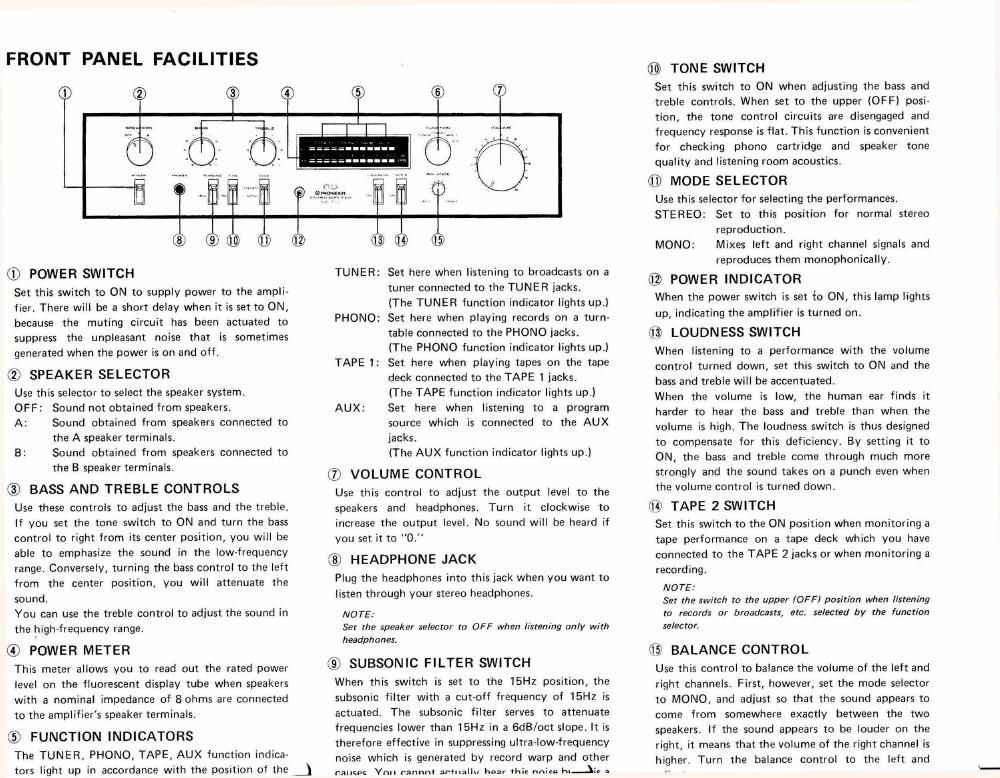
FRONT PANEL FACILITIES

w E E

@- E

(D POWER SWITCH
Set this switch to ON to supply power to the ampli-
fier. There will be a short delay when it is set to ON,
because the muting circuit has been actuated to
suppress the unpleasant noise that is sometimes
generated when the power is on and off.

(2) SPEAKER SELECTOR
Use this selector to select the speaker system.
OFF: Sound not obtained from speakers.

A: Sound obtained from speakers connected to
the A speaker terminals.
8: Sound obtained from speakers connected to

the 8 speaker terminals.

3) BASS AND TREBLE CONTROLS

Use these controls to adjust the bass and the treble.
lf you set the tone switch to ON and turn the bass
control to right from its center position, you will be
able to emphasize the sound in the low~frequency
range. Conversely, turning the bass control to the left
from the center position, you will attenuate the
sound.

You can use the treble control to adjust the sound in
the highrfrequency range.

(9 POWER METER

This meter allows you to read out the rated power
level on the fluorescent display tube when speakers
With a nominal impedance of Sohms are connected
to the amplifier's speaker terminals.

:57 FUNCTION INDICATORS
The TUNER, PHONO, TAPE, AUX function indica-

tors light up in accordance with the position of the A

is e

TUNER: Set here when listening to broadcasts on a
tuner connected to the TUNER lacks.
(The TUNER function indicator lights up)
PHONO: Set here when playing records on a turn-
table connected to the PHONO jacks.
(The PHONO function indicator lights up)
TAPE 1: Set here when playing tapes on the tape
deck connected to the TAPE 1 jacks.
(The TAPE function indicator lights up.)

AUX: Set here when listening to a program
source which is connected to the AUX
jacks.

lThe AUX function indicator lights up.)

(D VOLUME CONTROL
Use this control to adjust the output level to the
speakers and headphones. Turn it clockwise to
increase the output level. No sound will be heard if
you set it to ."0

® HEADPHONE JACK
Plug the headphones into this lack when you want to
listen through your stereo headphones.
NOTE:

Set the speaker selector to OFF when listening only with
headphones.

C9) SUBSONIC FILTER SWITCH

When this switch is set to the 15Hz position, the
subsonic filter with a cut-off frequency of 15Hz is
actuated. The subsonic filter serves to attenuate
frequencies lower than 15H: in a GdB/oct slope, It is
therefore effective in suppressing ultrarlow-frequencv
nOIse which is generated by record warp and other

rall

® TONE SWITCH
Set this switch to ON when adjusting the bass and
treble controls. When set to the upper (OFF) DOSI'
tion, the tone control circuits are disengaged and
frequency response is flat. This function is convenient
for checking phono cartridge and speaker tone
quality and listening room acoustics,
® MODE SELECTOR
Use this selector for selecting the performances.
STEREO: Set to this position for normal stereo
reproduction.
MONO: Mixes left and right channel signals and
reproduces them monophonically.

® POWER INDICATOR
When the power switch is set to ON, this lamp lights
up, indicating the amplifier is turned on,
(T3 LOUDNESS SWITCH
when listening to a performance with the volume
control turned down, set this switch to ON and the
bass and treble will be accentuated.
When the volume is low, the human ear finds it
harder to hear the bass and treble than when the
volume is high. The loudness switch is thus designed
to compensate for this deficiency. By setting it to
ON, the bass and treble come through much more
strongly and the sound takes on a punch even when
the volume control is turned down.
fl") TAPE 2 SWITCH
Set this switch to the ON position when monitoring a
tape performance on a tape deck which you have
connected to the TAPE 2 tacks or when monitoring a
recording.
NOTE:
Set the switch in the upper iaFFl position when listening

to records or broadcasts, arc. selected by the function
selector.

03 BALANCE CONTROL

Use this control to balance the volume of the left and
right channels, First, however, set the mode selector
to MONO, and adjust so that the sound appears to
come from somewhere exactly between the two
speakers. lf the sound appears to be louder on the
right, it means that the volume of the right channel is
higher. Turn the balance control to the left and

Page 2

Stereo Amplifier

SA-7'ID

OPERATING INSTRUCTIONS
HB, HE, S. S/G

IMPORTANT- 'fi

Tn preueltl electric shock, do nor remooe CDUPY. No
use: sen/rumble parts lllsnde. refer scroll-mg to
qualified serum pars-urine]

Always discimnert all the Pquipmelll from the
mains supply when ttlscolmectmg the signal lands.
The power and should be connected last, make sure
that the power switch 15 off.

Unplug the set from the wall soohot when it is riot
to be used /or an extended period of lime

FOR USE IN UNITED KINGDOM
CAUTION 240V: Mains supply voltage is
factory adjusted at 240V.

The wires In this mains [end are coloured in accord
ance with the following cord

Blue, Neulml

Brown Lino
As the colours of the wires in the mains lead of this
opporolus may not correspond with the coloured
marking identifying the terminals m ynur plug
proceed as follows.
The wire which is coloured blue must be connected
to Me terminal which is marked with the letter N or
coloured hlack
The wire which is coloured brown mus! be connect
ed lo [he terminal which is marhed with the letter L

or coloured red.

SPECIFICATIONS
Amplifier Section

Continuous Power Output of 65watts*per chan-
nel, min.,at 8 ohms from 20 Hertz to 20,000
Hertz with nomore than 0.02% total harmonic
distortion.

Continuous Power Output at lkHz (both channels
driven)
T.H.D. 0.02%, 8 ohms. . 70 watts per channel
Total Harmonic Distortion (20 Hertz to 20,000 Hertz,
8 ohms, from AUXl
32.5 watts per channel power output
No more than 0.015%
lntermodulation Distortion (50 Hertz : 7,000 Hertz
: 4 t 1, 8 ohms, from AUX]
continuous rated power output
. No more than 0.02%
32.5 watts per channel power output
. , No more than 0.015%
Damping Factor (20 Hertz to 20,000 Hertz, 8 ohms)

................ 60

Input (Sensitivity/Impedance)

PHONC ................ 2.5mV/50 kilohms

TUNER ............... 150mV/50 kilohms

AUX ................. 150mV/50 kilohrns

TAPE PLAY 1, 2 ......... 150mV/50 kilohms
Phono Overload Level (T.H.D, 0.01%, 1,000Hzl

PHONO ....................... 220mV
Output (Level)

TAPE REC 1, 2 ............. . . 150mV

Speaker . A, B, OFF

Frequency Response
PHONO lRIAA Equalization)
. , . 20Hz to 20,000Hz :0.2dB
TUNER, AUX, TAPE PLAY 1, 2
.. .1on to 100,000sz, dB

\

Tone Control

BASS .................... :IOdB (lOOHZ)
TREBLE ................ tIUdB (10,000Hzl
subsonic Filter .............. 15HZ (-SdB/Dctl
Loudness Contour (Volume control Set at -40dB
positionl ........ +6dB (100Hzl, +3dB l10,000Hzl
Hum and Noise (IHF, shon-circuiled, A networkl
PHONO ......................... 87dB
TUNER, AUX, TAPE PLAY 1, 2 ........ ioBdB
Hum and Noise (DIN, continuous Power/BOle
PHONO ................. 70dB/62dB

TUNER, AUX, TAPE PLAY 1,2. . . , 88dB/64dB

Miscellaneous
Power Requirements t . HE model;a.c. 220V, SO/GUHZ
HB model; a.t:. 240V, SO/GOHZ
S, S/G models;a.c. 110V/120V/220V/240V, 50/60HZ

Power Consumption ,,,,,,, HE, HB models;380W

S, S/G models; 130W

Dimensions ........ 420(W) >< 94(Hl x 347(D] mm

19-9/161Wl x 3-11/16lHlx13-11/16lDlin

Weight [Without package] ........ 7 Sky (16 lb 9011
Furnished Parts

Operating Instructions .................... 1

Fuse (5 and 5/6 models onlyl ............... 1

NOTE:

Speclllcallons and the deslgn sub/est to possible moduli
canon: wnhaur norlce due to lmprouements.

Measured pursuant 20 the Federal Trade Commixslon's

Trade Regulation rule on Pawer Output Claims for
Amplifiers,