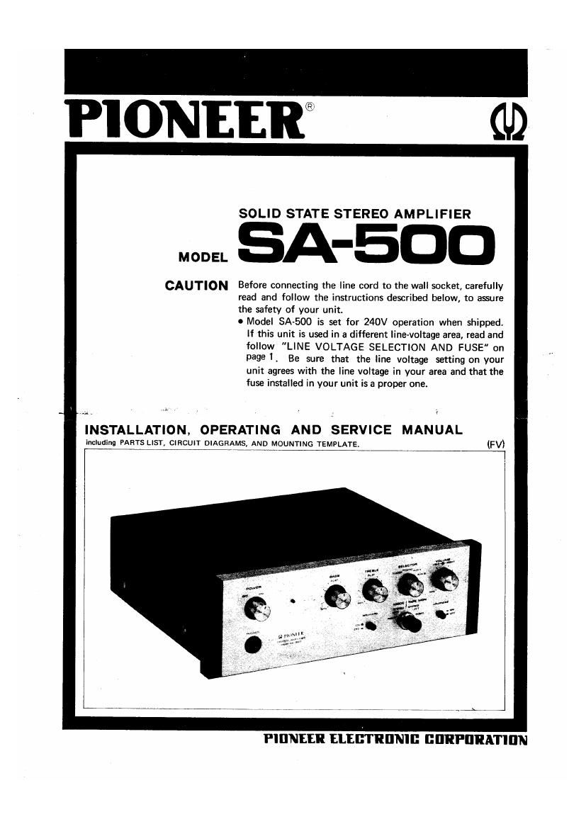
Pioneer SA 500 Service Manual 2

This is the 18 pages manual for Pioneer SA 500 Service Manual 2.
Read or download the pdf for free. If you want to contribute, please mail your pdfs to info@audioservicemanuals.com.

Page: 1 / 18
left right
Pioneer SA 500 Service Manual 2

Extracted text from Pioneer SA 500 Service Manual 2 (Ocr-read)


Page 1

PIONEEW 0.9

SOLID STATE STEREO AMPLIFIER

EBA-500

CAUTION Before connecting the line cord to the wall socket, carefully
read and follow the instructions described below, to assure
the safety of your unit.

0 Model SA-SOO is set for 240V operation when shipped.
If this unit is used in a different line-voltage area, read and
follow "LINE VOLTAGE SELECTION AND FUSE" on
page I . Be sure that the line voltage setting on your
unit agrees with the line voltage in your area and that the
fuse installed in your unit is a proper one.

INSTALLATION, OPERATING AND SERVICE MANUAL

including PARTS LIST, CIRCUIT DIAGRAMS, AND MOUNTING TEMPLATE. (FVI

Pl [lNEER ELEBTRIINIG GBRPDRATIIIN

Page 2

FEATURES OF SA-SOO

OSUPERIOR FREQUENCY RESPONSE:

By the use of all silicon transistors, a flat frequency
response with low distortion factor is obtained from
bass to treble.

OCOMPACT BUT VERSATILE:

In addition to the terminals for connection of a record
player, tuner and tape recorder, two sets of terminals
are provided for connection of auxiliary inputs to
permit reproduction of all kinds of program sources.

OSTABLE CIRCUIT DESIGN:

Separate printed-circuit boards are used for individual
unit blocks in order to stabilize operation and minimize
the possibility of faults.

INSTALLATION OF SA-SOO m...-

LINE VOLTAGE SELECTION AND FUSE ,

In order to remove the fuse, turn the fuse cap located
on the line voltage selector switch in the direction
indicated by an arrow. Then remove the fuse plug from
the unit. Put the fuse plug back so that the proper line
voltage marking can be seen through the cut in the edge
of the plug.

Whenever the set position of the selector switch is
changed. check the rating of the fuse. A 0.5ampere fuse
is to be used for either 220V or 240V operation and a
I~ampere fuse for any of 110V, 117V, or l3OV operation.
If the rating of the fuse is proper, install the fuse in the
fuse cap.

OREPLACING 0F FUSE

When the fuse is blown. remove the fuse cap and replace
the fuse with a new one.

-PIONEER_

0 VARIOUS ACCESSORY DEVICES:
A mode/tape monitor switch, loudness switch and loud-
speaker switch are provided for higher performance.

0 DESIGN NEWLYDEVELOPED BY PIONEER:

A product of PlONEERs new model series, designed for
both luxurious appearance and operational convenience.
Also, an AM/FM stereo tuner designed to match the
SA-500 in appearance is available separately.

SELECT THE PLACE OF INSTALLATION CON-
SIDERING THE FOLLOWING

IAvoid a place exposed to direct sunlight, near a
space heater or other heat-generating equipment, or
poorly ventilated.

OAvoid a dusty or humid place.

'Avoid a place that is unstable or frequently incurs
vibration.

FUSE CAP FUSE FUSE PLUG SOCKET
Fig. 1
Take off the fuse cap by turning it with a coin,
in the direction indicated by the arrow.