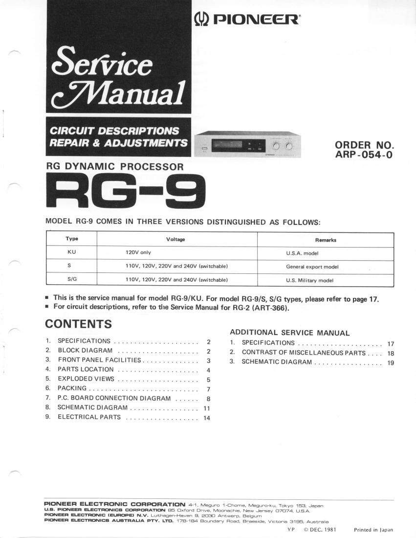
Pioneer rg 9 service manual

This is the 20 pages manual for pioneer rg 9 service manual.
Read or download the pdf for free. If you want to contribute, please mail your pdfs to info@audioservicemanuals.com.

Page: 1 / 20
left right
pioneer rg 9 service manual

Extracted text from pioneer rg 9 service manual (Ocr-read)


Page 1

1. SPECIFICATIONS Processor Section Maximum Output Voltage . . 6.5V (1 kHz, T.H.D. : O.5o/o R 1 : 47kC2, DYNAM lC EXPANSION: 16dB) Total Harmonic Distortion . 0.05% (Output: 1V, lkHz, DYNAMIC EXPANSION:16d8) Dynamic Expansion 4, 7 , 10, 13 16dB Gain lmpulse Response AttackTime .. .0.3msec Release Time 120msec f nput lmpedance 50kO (2OHz to 20kHz) Output lmpedance 300S, (lkHz) Residual Noise 10pV (lHF A, DYNAMIC EXPANSION: 16dB) Signal to Noise Ratio (lHF A, Shortcircuited, DYNAM lC EXPANSION: 16dB) 100d8 (at 1V) 1 16dB (at 6.5V) Miscellaneous Power Requirements AC 1 20V, 60Hz Power Consumption 10W Dimensions 420(W) x 99(H) x 336(D) mm 16-9116(W) x 3-718(H) x 13-1l4lD) in Weight (without package) 4.4k9 (9lb 11ozl Furnished Parts Connectioncordwithpinplugs .....2 Operating instructions 1 NOTE: Specifications and the design subject to possible modification without notice due to improvements. LchPROCESSOR GAIN CONTROL AMP ooNh s2-3 "T: i8ln$o"r." ur{swrrcHEo AC t20V60 Hz METER swrTcHEsS I TAPE MONITOR ON - OFF s2 PROCESSOR S-OFF s3 DYNAMTC EXPANSTON 4de-7atB-tOdB-t3d8-t5dB 54 POWER ON -OFF Thc und.rlin.d indicotca tha !uitch po3ition 2 DYNAMIC EXPANSION 4dB 7dB 1 0dB 13dB 1 6dB Upward Gain +2dB +4dB +6dB +8dB +1 odB Downward Gain -2dB -3dB -4dB -5dB --‚¬dB 2. BLOCK DIAGRAM I NPUT3l6mV OUTPUT IV TAPEREC3l6mV PLAY lv Rch TAPEMOttllTOR POWER RG DETECTOR CIRCUIT DYNAMIC EXPANSION METER TUBE DRIVER l-MAxl |?oel @ ltodBl lT3-‚¬l [6d-d otrotrtrtrootrtrtroo trtrtrtrotro trtroootroootrotroQtrBtrotrtr 16t514t3t2illo9 t2345678 PROCESSOR RELAY DRIVER CIRCUIT

Page 2

3. FRONT PANEL FACILITIES e POWER SWTTCH Power is supplied to the model RG-9 when this switch is depressed. The power indicator comes on as soon as the power is supplied. @ PowER rNDrcAToR This comes on as soon as the RG-9's power switch is set to ON to indicate that power is being supplied. -‚¬) DYNAMTC EXPANSTON METER This meter allows you to read out the gain boost with respect to the input signal in decibels. (See additional description on page 6). @ DYNAMIC EXPANSIoN INDIcAToRS The 4dB, 7dB, 10d8, 13d8, 16dB indicators light up in accordance with the position of the dynamic expansion selector. @ PRocESsoR SWITcH Depress this switch (ON) to produce an expansion effect with the signals fed from the PROCESSOR INPUT jacks. The dynamic expansion indicator will come or, and signals featuring an expansion effect only will be fed out from the model RG-9's OUTPUT jacks. In the OFF posi- tion, the RG-9 circuitry is bypassed. This position allows for instant comparison between the expanded and the un- processed signals. NOTE:When the RG-9's power switch is set to the OFF position and the processor switch is also set fo OFF, the signal which has bypassed the processor circuitry is nnde available at the OUTPUT jacks. There will, however, be no output if the input level control is set to the '0' position. Make sure that this control I's set to the'lO' position. @ TAPE MONIToR INDIcAToR This comes on when the tape monitor switch is depressed. @ TAPE MONTTOR SWTTCH Depress this switch to monitor the sound on the tape as it is being recorded or when playing back a tape using a tape deck connected to the RG-9's TAPE jacks. (The tape monitor indicator comes on.) Set the switch to OFF when not in use. @ DYNAMIc EXPANSIoN SELEcToR This selector selects maximum gain boost value with respect to the input level, i.e.: ratio of gain increase between large input signal and small ipput signal. Max- imum gain boost increases as the selector is turned clockwise. Set the selector to the most desirable position while listening to the reproduced sound. * Dynamic Expansion Dynamic expansion is defined as the sum of the downward expansion (where small inputs are expanded down) and upward expnsion (where large inputs are expanded up). -‚¬) |NPUT LEVEL CONTROL Use this control to adjust the input level at which the expansion effect is initiated. Clockwise rotation increases the expansion with respect to small signal levels (increases expansion sensitivity). Adjust the control for desired effect according to program source.