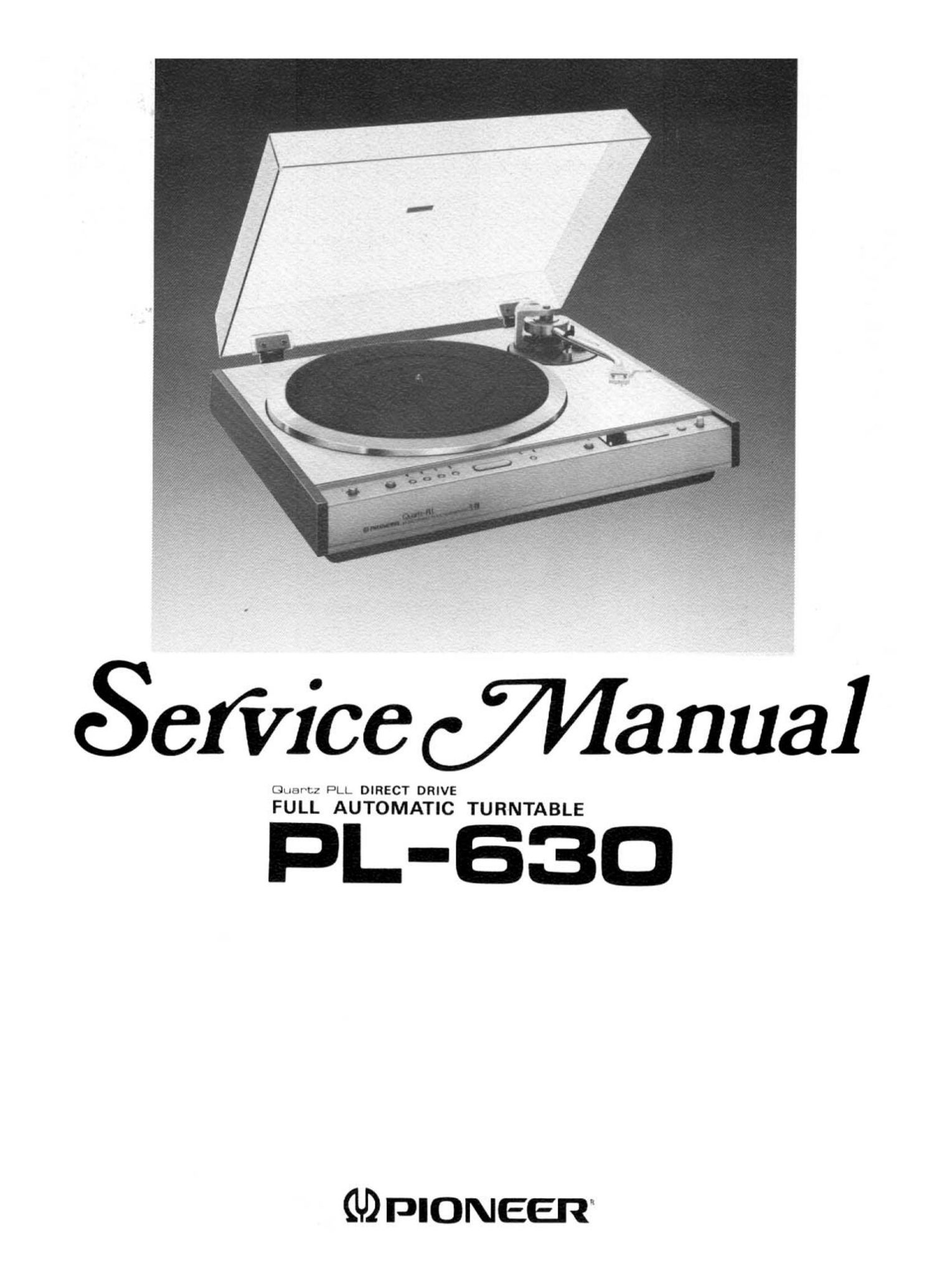
Pioneer pl 630 service manual

This is the 41 pages manual for pioneer pl 630 service manual.
Read or download the pdf for free. If you want to contribute, please mail your pdfs to info@audioservicemanuals.com.

Page: 1 / 41
left right
pioneer pl 630 service manual

Extracted text from pioneer pl 630 service manual (Ocr-read)


Page 2

MODEL PL-630 COMES IN FIVE VERSIONS DISTINGUISHED AS FOLLOWS:

Type Voltage Remarks

KCT 120V only Canada model (Without cartridge)

KUT 120V only U.S.A. model (Without cartridge)

HGT 7 220V - 240:! J 77 Europe or Oceania model (Without cartridge)
ST 110V -- 120V, 220V - 240V (Switchable) General export model (Without cartridge)
SIG 110V - 120V, 220V - 240V (Switchable) U.S. Military model (Within cartridge)

a This service manual is applicable to the PL-630/KCT, KUT. For servicing of the other types please refer
to the additional service manuals.

CONTENTS

1. SPECIFICATIONS ..................... 3
2. PANEL FACILITIES. . . .' ................ 4
3. DISASSEMBLY ....................... 6
4. PART LOCATION ..................... 8

5. SCHEMATIC DIAGRAMS, P.C. BOARD
PATTERNS AND PARTS LIST

5.1 Schematic Diagram ................. 9
5.2 Control (A) Assembly (PWX-035) ....... 11
5.3 P.C. Board Connection Diagram ......... 12
5.4 Control (B) Assembly (XWX-007) ....... 15
5-5 Switch Assembly (XWX-OOB)

and Lamp Assembly (XWX-OOQ) ........ 15
5.6 Tonearm Drive Assembly (PWX-027) ..... 15
5.7 Power Supply Assembly .............. 17
5.8 Oscillator Assembly (PWX-022) ......... 17
5.9 Drive Control Assembly (PWG-017) .. ..... 18
EXPLODED VIEW
6.1 Outer Parts ...................... 19
6.2 Cabinet ......................... 21
6.3 Tonearm (Arm Base) ................ 23
6.4 Under Base .............. A ........ 25
6.5 D. D. Motor (PXM067) .............. 26
6.6 Packing ......................... 27

7. DESCRIPTION OF OPERATION

7.1 Mechanical Section .................
7.2 Control Section (Electrical Section) ......
7.3 Actual Operation (17cm record) ........
7.4 Actual Operation of Mechanical Section . . .

. ADJUSTMENT ........................
. D.D. MOTOR CIRCUIT DESCRIPTIONS

AND TROUBLE SHOOTING
9.1 Block Diagram ....................

9.2 Motor Operation ...................

9.3 Operation of The PD1003 IC
(Oscillator Stage) ..................

9.4 Operation of The PA2004 IC
(Comparator Control) ...............

9.5 Operation of The PA2005 IC
(Drive Control) ....................

9.6 Trouble Shooting Chart ..............

29
31
34
35
36

39
41

43

43

43
48