Pioneer pl 41 c owners manual

This is the 11 pages manual for pioneer pl 41 c owners manual.
Read or download the pdf for free. If you want to contribute, please mail your pdfs to info@audioservicemanuals.com.

Page: 1 / 11
left right
pioneer pl 41 c owners manual

Extracted text from pioneer pl 41 c owners manual (Ocr-read)


Page 1

PI ON EER

WORLD-FAMOUS BRAND IN HI-FI REPRODUCTION

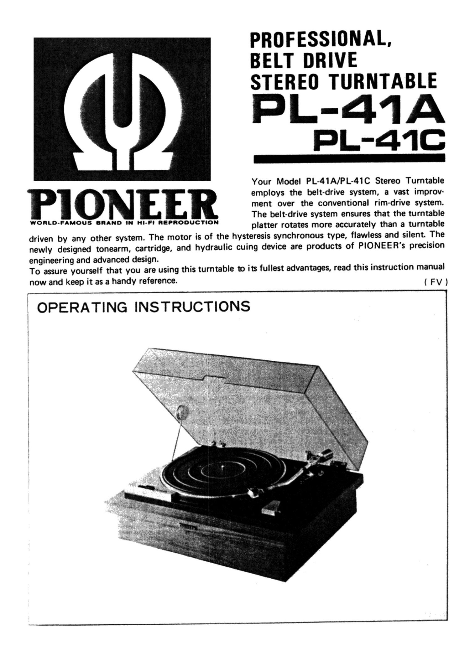
PROFESSIONAL.
BELT DRIVE
STEREO TURNTABLE

PL-41A
PL-41C

Your Model PL-41A/PL-41C Stereo Turntable
employs the belt-drive system, a vast improv-
ment over the conventional rim-drive system.
The belt-drive system ensures that the turntable
platter rotates more accurately than a turntable

driven by any other system. The motor is of the hysteresis synchronous type, flawless and silent. The
newly designed tonearm, cartridge, and hydraulic cuing device are products of PIONEER's precision

engineering and advanced design.

To assure yourself that you are using this turnta

now and keep it as a handy reference.

OPERATING INSTRUCTIONS

ble to its fullest advantages, read this instruction manual

(FV)

Page 2

The instructions covered herein also apply to Model PU-41A which is the PL-41A less the wooden base, and to Model

PL-41C which is the Model PL-41A less the cartridge.

ASSEMBLY

NOTE: The turntable platter will be found under a cardboard
sheet in the lower portion of the packing case.

1. REMOVE THREE MOTOR-BOARD CLAMPING
SCREWS.

The clamping screws are tipped with red paint. When they are
removed, the motor-board is freed from the base plate and
supported by three suspension springs with plastic cushions.

(Fig. 1)

2. LINE VOLTAGE AND LINE FREQUENCY

A. LINE VOLTAGE SELECTOR PLUG

The PL-41A is normally set for 240-volt operation prior to
shipment. If the voltage in your area is 220, 130, 117, or 110
volts, pull out the line voltage selector plug and re-insert it so
that the correct voltage reading appears in the cut provided in
the selector plug. (Fig. 2)

B. CAPSTAN EXCHANGE

Two kinds of capstans are furnished with the Model PL-41A;

one for 50Hz Operation and the other for 60-Hz operation. The

50-Hz capstan has_a larger diameter, and the 60-Hz capstan, a

smaller diameter with a groove in the lower part. The Model

PL~41A is usually set for Operation of the line frequency in the

area to which it is shipped; however, if you move to some other

area where the line frequency is different, you must change the
capstan for proper turntable Speeds. Find out the line frequency
in your area and set the proper capstan in your turntable as

follows: (Fig. 3)

0 You will find a capstan set up on the motor shaft and a spare
capstan laid on the base plate.

0 Loosen two setscrews on the side of the capstan in use with
the small screwdriver furnished in the accessory group, and
remove them. Then pull out the capstan. from the motor
shaft.

0 Loosen the clamp that is holding the spare capstan, remove
the capstan from the resting place. and install it on the motor
shaft.

0 Before. tightening the setscrews, set the capstan in position
on the motor shaft so that the center of the belt is aligned
with that of the belt guide of the shift lever. (Fig. 4)

0 Set the line frequency switch to the proper frequency
position. (Fig. 3)

) l.» nemvs cuwmc sceews l

z.
lz

2 AND 3'

Fig. l
a&.& VOLTAGE
, setscroa ewe
I lov l I 7V .30V 220V 240V
@- ,9 '\ a: a 1-,» V}
I
Q ./@ 9 3: (9
Fig. 2

CAPSTAN FOR USE
IN TFE 30H: ARE

A GROOVE l5-


CAPSTAN FOR USE
N THE 90H: AREA

SPEED SELEC 70R PUSHOUTPONS

'33" is in me peesseo posmors

CAPSTAN

The real. poslon an we can pan
lo the nest» show no as "saluted
1' W S iur.

,_-... sF-w-«e

Fig. 3

, .._...________. .... .-v-

1
l
l