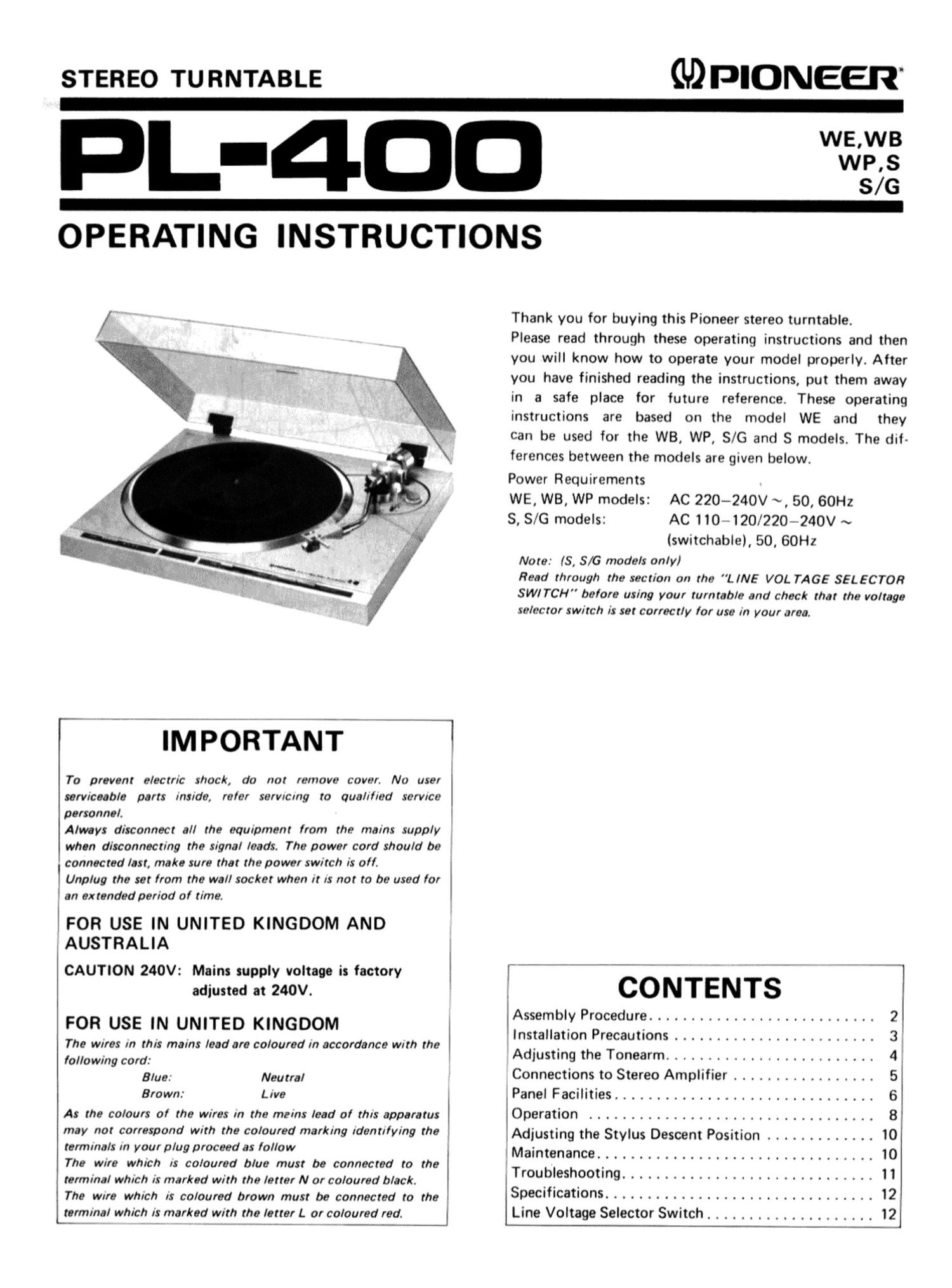
Pioneer pl 400 owners manual

This is the 12 pages manual for pioneer pl 400 owners manual.
Read or download the pdf for free. If you want to contribute, please mail your pdfs to info@audioservicemanuals.com.

Page: 1 / 12
left right
pioneer pl 400 owners manual

Extracted text from pioneer pl 400 owners manual (Ocr-read)


Page 1

STEREO 'ru RNTABLE (ID PIONEER"

WE,WB
L-4DD
S/G

OPERATING INSTRUCTIONS

/ Thank you for buying this Pioneer stereo turntable.

Please read through these operating instructions and then
you will know how to operate your model properly. After
you have finished reading the instructions, put them away
in a safe place for future reference. These operating
instructions are based on the model WE and they
can be used for the WB, WP, 8/6 and S models. The dif-
ferences between the models are given below.

Power Requirements

WE, WB, WP models: AC 220-24OV ~, 50, 60Hz

S, 5/6 models: AC 110-120/220-240V ~
(switchable), 50, 60Hz

Note: (S, 8/6 models only)

Read through the section on the L lNE VOL TAGE SELECTOR
. SW/ TCH" before using your turntable and check that the voltage
3 selector switch is set correctly for use in your area.

r" ' IMPORTANT-Tm """" 7.

To prevent electric shock, do not remove cover. No user
serviceable parts inside, refer servrcmg to qualified servrce l
personnel. I
Always disconnect all the equipment from the mains supply
when disconnecting the signal leads. The power cord should be
connected last, make sure that the power switch is oil. l
Unplug the set from the wall socket when it is not to be used for b
an extended period of time.

FOR USE IN UNITED KINGDOM AND

AUSTRALIA }
. . . l- --"'- ____ '
CAUTION 240V. Mains supply voltage is factory i : CONTENTS
adjusted at 240V. .
Assembly Procedure ........................... 2
FOR USE IN UNITED KINGDOM . . .
, y > Installation Precautions ........................ 3
The Wires in this mains lead are coloured in accordance With the . .
_ Adjusting the Tonearm ......................... 4
lollowmg cord. . . .
3,, New, Connections to Stereo Amplifier ................. 5
Brown: Live , Panel Facilities ............................... 6
As the colours of the wires in the mains lead of this apparatus l Operation .................................. 8
may not correspond With the coloured marking identifying the :Adjusting the Stylus Descent Position ............. 10
emmL " Voupugpoceed 3 0 . Maintenance ................................. 10
The wire which IS coloared blue must be connected to the Tro bleshoot'n 1 1
terminal which is marked with the letter N or coloured black. i U. . ' I g """"""""""""""""
The wrre which is calcured brown must be connected to the l SpeCIfications -------------------------------- 2
terminal which is marked with the letter L or coloured red. Line Voltage Selector Switch .................... 12

Page 2

ASSEMBLY PROCEDURE

1: \ _ , - - _ /- Dust cover
\ / , -,

Center shalt

A Counterwerght

Rubber platter mat


Platter
Anti-skate knob
Arm-elevation lever
Cabinet Arm rest
(/< 0
W »3
I
Headshell
Speed selector button Record size selector Cartridge LOCR'W collar
Repeat button Start/Cut button -

1. CHECK THE ACCESSORIES

The styrene pad contains the parts shown in the figure.
Check that they are all inside. The EP adapter is used for
records with a large center hole.

5? adapter

4: Styrene pad COunterweight

Headshell

2. REMOVING TRANSIT SCREWS

Remove three transit screws with a Phillips screwdriver as
shown below. Then remove platter and three platter pads.

Transit screw
Platter

Center shalt Platter pad

3. REMOVING DUST COVER

1. Fully open the dust cover.
2. Hold the dust cover, and lift it off by pulling it straight
upward.

4. MOUNTING THE PLATTER AND RUBBER
PLATTER MAT

Refer to the assembly figure, and place both the platter and
the rubber platter mat down over the center shaft. The
platter is heavy, so use both hands to lift it horizontally
over the shaft and into position.

5. MOUNTING THE HEADSHELL

Insert the headshell (with the cartridge) into the end of the
tonearm, and rotate the locking collar in the direction
indicated by the arrow in the figure until it staps. Then
secure it.

6. MOUNTING THE COUNTERWEIGHT

Slide the counterweight onto the counterweight shaft on
the rear of the tonearm and push it forward. Then rotate it
two or three turns in the direction of the arrow.

7. MOUNTING THE DUST COVER

To install, insert the hinges of the dust cover into the hinge
sockets of the cabinet, and push the dust cover downward.