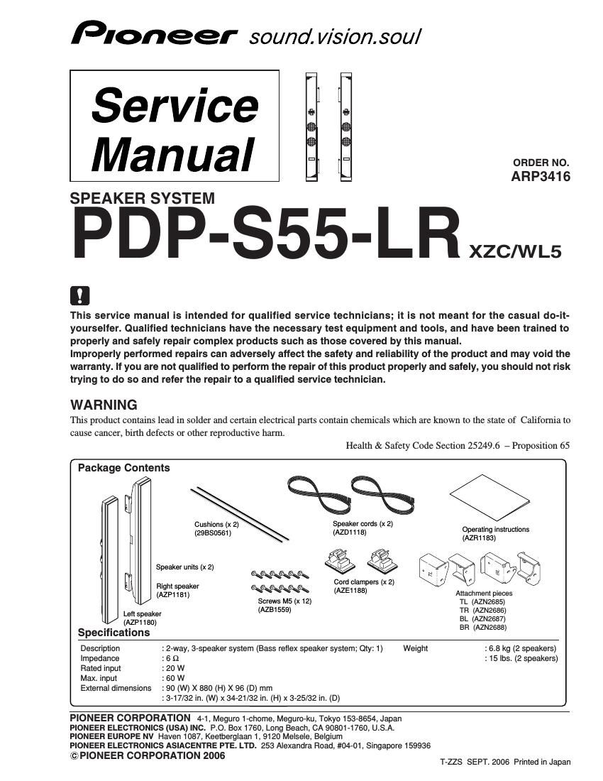
Pioneer pdps 55 service manual

This is the 3 pages manual for pioneer pdps 55 service manual.
Read or download the pdf for free. If you want to contribute, please mail your pdfs to info@audioservicemanuals.com.

Page: 1 / 3
left right
pioneer pdps 55 service manual

Extracted text from pioneer pdps 55 service manual (Ocr-read)


Page 1

2 1 23 4 1234 C D F A B E PDP-S55-LR Speaker Unit LSpeaker Unit R Carton Box/ TOP Lch Rch Carton Box/ BOTTOM (Cushion : include 2 pieces) (Cord Clamper : include 2 pieces) (Speaker Cord : include 2 pieces) 211 5 478 10 16 313 11 12 14 56 15 9 2. EXPLODED VIEWS AND PARTS LIST Parts marked by "NSP" are generally unavailable because they are not in our Master Spare Parts List. The mark found on some component parts indicates the importance of the safety factor of the part. Therefore, when replacing, be sure to use parts of identical designation. NOTES: 2.1 PACKING -Do not pinch the connecting cord when attachting the speaker system. -Make sure the L and R Holders are attached to the correct speakers. -The speaker system is not serviceable and must be exchanged. 1. REASSEMBLY AND DISASSEMBLY PRECAUTIONS 1Protection Sheet (S55) AZH1296 2Bag Poly (S55) AZE1193 3Bag Poly (SP Manual) AZE1155 4Carton Box (S55) AZH1261 5Cushion Box (61SP) 29M00841 6Cushion Piece AZH1301 7Label U (S55) AZR1186 8Cord Clamper AZE1188 9Speaker Cord AZD1118 10 Cushion 29BS0561 PACKING Parts List 11 Attachment Piece TL AZN2685 12 Attachment Piece TR AZN2686 13 Attachment Piece BL AZN2687 14 Attachment Piece BR AZN2688 15 Screw (PMB50P120FBN) AZB1559 16 Operating Instructions AZR1183 (Japanese, English, French, German, Italian, Dutch, Spanish) Mark No. Description Part No. Mark No. Description Part No.

Page 2

3 1 234 1 23 4 C D F A B E PDP-S55-LR LLR 2 5 R 2 5 3 3 [ Front View ] [ Back View ] 3 3 1 4 2.2 SPEAKER UNIT 1Speaker Unit (L) AZP1180 2Holder L (S55) AZN2683 3Screw (M4 x 8) AZB1522 4Speaker Unit (R) AZP1181 5Holder R (S55) AZN2684 3Screw (M4 x 8) AZB1522 Mark No. Description Part No. SPEAKER UNIT Parts List Main VC Tweeter INPUT BlueRed Black Black 100 µF/50 V 3.3 µF/50 V C1 C2 Sub VC White Black L1 18 mH Network Assy Woofer x2 3. SCHEMATIC DIAGRAM