Pioneer pd t 307 service manual

This is the 11 pages manual for pioneer pd t 307 service manual.
Read or download the pdf for free. If you want to contribute, please mail your pdfs to info@audioservicemanuals.com.

Page: 1 / 11
left right
pioneer pd t 307 service manual

Extracted text from pioneer pd t 307 service manual (Ocr-read)


Page 1

GD PIONEER'

The Art of Entertainment

Scfiice : f_ WW?

Wanna] W -

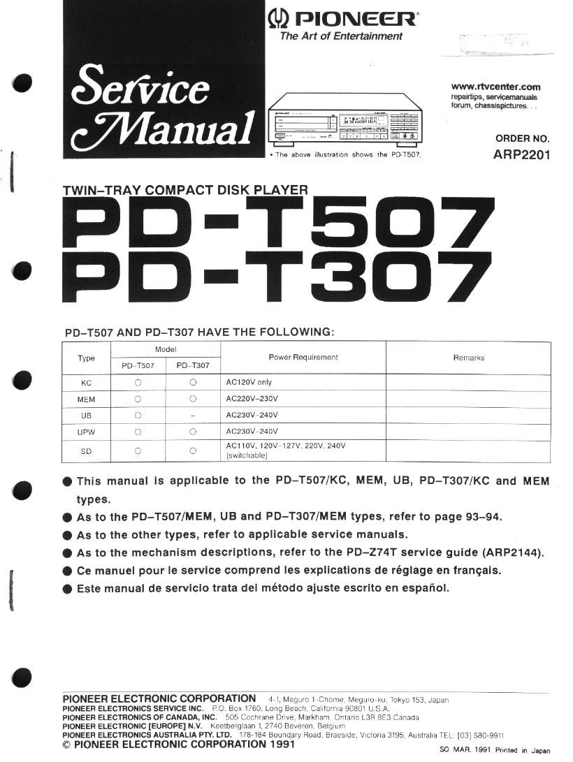
TWIN-TRAY COMPACT DISK PLAYER

PD-T5D7
PD-T3D7

PD-T507 AND PD-T307 HAVE THE FOLLOWING:

ORDER NO.
. The above Illustration shows the PD»T507. ARP2201

Model
Type 7 , Power Requirement Remarks
Posrsov PD T307
KC g ACIZOV only
MEM . Cg» Aczzovrzaov
UB 7 ACZ3OV 240v
upw x7 .1 5 AC230V 240V if
so ACllOV.120V7127V.220V.240V 7 7 7
(sthchable)

O This manual is applicable to the PD-T507/KC, MEM, UB, PD-T307/KC and MEM
types.

0 As to the PD-T507/MEM, U3 and PD-T307/MEM types, refer to page 93-94.

0 As to the other types, refer to applicable service manuals.

Q As to the mechanism descrlptlons, refer to the PD-Z74T servlce guide (ARP2144).

0 Ce manuel pour le service comprend les explications de réglage en franqais.

O Este manual de servlclo trata del método aiuste escrito en espafiol.

PIONEER ELECTRONIC CORPORATION 4,1 Meguro LChome Megmo kn Tokyo i53 Japan
PIONEER ELECTRONICS SERVICE INC. P O Box 1760 Long Beach CaIl'Dillld 90801 U S A

PIONEER ELECTRONICS OF CANADA, INC. 505 Cochvane DHVE Markham Ontario L3Fi 8E3 Canada
PIONEER ELECTRONIC [EUROPE] N.V. Keetberglaan 1 2740 Beveren Belgium

PIONEER ELECTRONICS AUSTRALIA PTY. LTD. 1787184 Boundaiy Road Braesme, VlCIUHd 3195 AusilaIla TEL [03158079911

© PIONEER ELECTRONIC CORPORATION 1991 so MAR. 1991 pm, in Jam

Page 2

2. REMOVING AND MOUNTING OF EACH BLOCK

. REMOVAL OF TRAY I AND TRAY II

1. Open the [my I.
2. Insert the flat blade screwdriver into the slit in the left of
tray 1. Pull out the tray I by pushing the screwdriver.

Screwd river

Slit position at tray I

When remove the tray ll. open It first, insert the llat blade
screwdriver into the slit in the right of tray II, and pull out the
tray by pushing the screwdriver.

Screwd river

Gear || Slit position of tray ll

Fig. 1

. MOUNTING OF TRAY |

I. Set the disc II to the clamp position and open the tray 1.

2. Align the ISI tooth of tray I to ungrooved portion of gear I,
and insert the tray I.

. mark \
Ungrooved portion :
0 mark /

lst tooth

Fig. 2

. MOUNTING OF TRAY II

I. Set the disc I to the clamp position and open the tray II.
2, Align the lst tooth of tiny II to [:1 marked position of gear
II, and insert the tray ll.

Align horizontally to El mark.

\

I

1 st tooth

Fig. 3