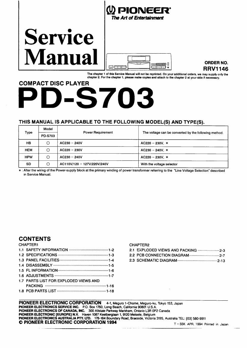
Pioneer pds 703 service manual

This is the 29 pages manual for pioneer pds 703 service manual.
Read or download the pdf for free. If you want to contribute, please mail your pdfs to info@audioservicemanuals.com.

Page: 1 / 29
left right
pioneer pds 703 service manual

Extracted text from pioneer pds 703 service manual (Ocr-read)


Page 1

0,9 PIONEER'

WMdEntertalmmlt

Service
Manual 3:35:12:

The chapter 1 01min Service Manual will not be reprinted. On your additional orders. we may supply only the
chapter 2. For the chapter 1. please mains copies and attach to lire chapter 2 at your side ii necessary.

COMPACT DISC PLAYER

¥ PD-S703

THIS MANUAL IS APPLICABLE TO THE FOLLOWING MODEL(S) AND TYPE(S).

Type Modal Power Requirement The voltage can be convened by lhe lollowing methodr
PD-S703
H5 0 A0230 - 240V A0220 - 230V. *
HEM O A0220 - 230V AC230 - 240V. *
HPW O A0230 - 240V AC220 - 230V. *
SD 0 ACIIOV/120 - 127V/220V/240V Wilh the voltage seleclor

1: : Alter the wiring of the Power-supply block at the primary winding of power translormer referring lo the 'Line Voltage Selection" described
in Service Manual.

CONTENTS
CHAPTER1 CHAPTERZ
1.1 SAFETY INFORMATION ----------- ~1-2 2.1 EXPLODED VIEWS AND PACKING ------------------ 2-3


1.2 SPECIFICATIONS ----- -1-3 2.2 PCB CONNECTION DIAGRAM -v~~2-7
1.3 PANEL FACILITIES' 1-4 2.3 SCHEMATIC DIAGRAM ---------- "-243
1_4 DISASSEMBLY ........................ .1-5
1.5 FL INFORMATION .......................... '1-6

1.6 ADJUSTMENTS ............................. .1.7

1.7 PARTS LIST FOR EXPLODED VIEWS AND
PACKING .......................................... 1-16

1.8 PCB pAfiTS LIST ........................................ 1.15

PIONEER ELECTRONIC CORPORATION 4-1. Meguro 1-Chome. Megurotku. Tokyo 153. Japan

PIONEER ELECTRONICS SERVICE INC. Roi BOX 1750. Long 5630. Calliornia 90801 U.S.A.

PIONEER ELECTRONICS OF NADA. NC. 300 Allslale Parkway Markham. Ontario L3H 0P2 Canada

PIONEER ELECTRONIC [EUROPE] N.V. Haven 1037 Keetberglaan I. 9120 Melsele. Belgium

PDNEER ELECTRONICS AUSTRALIA PW. LTD. 178-1 Boundary Road. BIESIGO. Victoria 3195, Australia TEL: [03] 580-99

0 PIONEER ELECTRONIC CORPORATION I 994 T _ 35K APR 1994 primed in Japan

Page 2

PD-S703

- VARO!

- (FOR EUROPEAN MODEL ONLY)

AVATTAESSA JA SUOJALUKITUS
OHITETTAESSA OLET ALTTIINA
NAKVMATTOMALLE LASERSATEILYLLE
ALA KATSO SATEESEEN

- ADVERSEL:

USYNLIG LASERSTRALING VED ABNING
NAR SIKKERHEDSAFBRVDERE ER UDE AF
FUNKTION UNDGA UDSAETTELSE FOR
STRALING.

" VAHNING

OSVNLIG LASERSTRALNING NAFI DENNA
DEL AR OPPNAD OCH SPARREN

CHAPTER 1
1.1 SAFETY INFORMATION

AR URKOPPLAD. EETRAKTA EJ STRALEN

LASER

Kuva I
Lasctsaieilyn
varoitusmerltlri

r WARNING!

EMITS INVISIBLE INFRARED RADIATION
WHICH IS DANGEROUS T0 EYES. THERE IS
A WARNING SIGN ACCORDING TO PICTURE
I INSIDE THE DEVICE CLOSE TO THE LASER
DIODE

DEVICE INCLUDES LASER DIODE WHICH

IMPORTANT
THIS PIONEER APPARATUS CONTAINS
LASER OF CLASS I.
SERVICING OPERATION OF THE APPARATUS
SHOULD BE DONE BY A SFECIALLV
INSTRUCTED PERSON.

- LASER DIODE CHARACTERISTICS .-

LASER

Picrure 1
Warning sign Ior
laser radiation

MAXIMUM OUTPUT POWER: 5 mw
WAVELENGTH: 730-785 nm

LABEL CHECK

HB and HEM types

CLASS 1
LASER PRODUCT

HEM type

vmi

Autunn ]- neg-untu- emu-tu-
uu an: uuun. nun-nun.
Inuuuuyuc. Lu nuo nun-«n.

vmxch

Olynllq lllcrltrllnlnq nlr cum-- «I
n bppnld och .pcrmr u- urknpylud.

utnxu n1 strum.

FIEAFI VIEW

mm.
mm um". m'fih*"'" "
H
WW II m
M"
mu-ammu- I- III
mammal-mum
Inna

CAUTION
INVISIBLE LASER
RADIATION WHEN
AVOIO EXPOSURE
TO BEAM

"3 type

OPEN,

PRWIOIB

mm

Additional Laser Caution

l. Laser Interlock Mechanism

The position of the Switch (3501) for detecting loading
state is detected by the system microprocessor. and
the design nrevents laser diode oscillation when the
switch ($601) is not on CEW terminal side (CCMF
signal is OFF or high level).

Thus. the interlock will no longer function if the switch
(8601)is deliberatelv set to m terminal sida(low level).
The interlock also does not function in the test mode *.
Laser diode oscillation will continue. if pin 1 of
M51593FP (ICIOI) on the PRE AMP BOARD ASSY
mounted on the pickup assembly is connected to GND.
or pin 19 is connected to low level (ON). or else the
terminals of 0101 are shorted to each other (fault
condition).

2. When the cover is opened. close viewing of the

objective lens with the naked eye will cause exposure
to a Class I laser beam. m;

ax Refer to page 1-8.