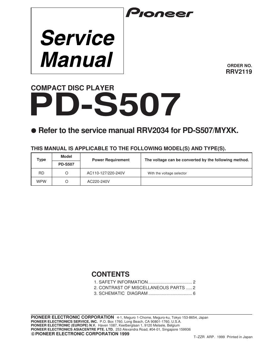
Pioneer pds 507 service manual

This is the 9 pages manual for pioneer pds 507 service manual.
Read or download the pdf for free. If you want to contribute, please mail your pdfs to info@audioservicemanuals.com.

Page: 1 / 9
left right
pioneer pds 507 service manual

Extracted text from pioneer pds 507 service manual (Ocr-read)


Page 1

PD-S507 2 This service manual is intended for qualified service technicians; it is not meant for the casual do-it-yourselfer. Qualified technicians have the necessary test equipment and tools, and have been trained to properly and safely repair complex products such as those covered by this manual. Improperly performed repairs can adversely affect the safety and reliability of the product and may void the warranty. If you are not qualified to perform the repair of this product properly and safely, you should not risk trying to do so and refer the repair to a qualified service technician. 1. SAFETY INFORMATION LASER DIODE CHARACTERISTICS MAXIMUM OUTPUT POWER: 7 mw WAVELENGTH: 780 Ð 785 nm IMPORTANT THIS PIONEER APPARATUS CONTAINS LASER OF CLASS 1. SERVICING OPERATION OF THE APPARATUS SHOULD BE DONE BY A SPECIALLY INSTRUCTED PERSON. LABEL CHECK WPW type Only REAR 2. CONTRAST OF MISCELLANEOUS PARTS NOTES :ÖParts marked by Ò NSP Ó are generally unavailable because they are not in our Master Spare Parts List. ÖThe mark found on some component parts indicates the importance of the safety factor of the part. Therefore, when replacing, be sure to use parts of identical designation. ÖReference Nos. indicate the pages and Nos. in the service manual for the base model. ÖWhen ordering resistors, first convert resistance values into code form as shown in the following examples. Ex. 1 When there are 2 effective digits (any digit apart from 0), such as 560 ohm and 47k ohm (tolerance is shown by J = 5%, and K = 10%). 560 W = 56 ´ 10 1 = 561 ...................................................RD1/4PU 5 6 1 J 47k W = 47 ´ 10 3 = 473 ..................................................RD1/4PU 4 7 3 J 0.5 W = R50 ......................................................................RN2H å 5 0 K 1 W = 1R0 .........................................................................RS1P 1 å 0 K Ex. 2 When there are 3 effective digits (such as in high precision metal film resistors). 5.62k W = 562 ´ 10 1 = 5621...........................................RN1/4PC 5 6 2 1 F

Page 2

PD-S507 3 NSP MOTHER BOARD ASSY PWM2240 PWM2242 PWM2243 P5-1 MAIN BOARD ASSY PWZ3762 PWZ3764 PWZ3765 P5-2 POWER BOARD ASSY PWZ3770 PWZ3771 PWZ3772 P6-1 SWITCH BOARD ASSY PWZ3766 PWZ3767 PWZ3767 P6-2 NSP MODE BOARD ASSY PWZ3768 PWZ3769 PWZ3769 P6-3 NSP HEADPHONE BOARD ASSY PWZ3773 PWZ3776 PWZ3776 PACKING P3-2 Protector R PHA1331 PHA1330 PHA1330 P3-3 Packing Case PHG2314 PHG2331 PHG2331 P3-6 Operating Instructions PRE1270 Not used Not used (English/French/German/Italian/ Dutch/Swedish/Spanish/Portuguese) P3-6 Operating Instructions Not used PRE1271 PRE1271 (English/Spanish/Chinese) P3-8 Remote Control Unit XWW1001 PWW1140 PWW1140 (CU-PD096) (CU-PD092) (CU-PD092) P3-12 NSP Warranty Card ARY7022 Not used PRY1002 NSP Caution 220V Card Not used ARR7003 Not used No.1 EXTERIOR P5-5 AC Power Cord PDG1043 PDG1013 ADG1123 P5-6 Power Transformer PTT1236 PTT1238 PTT1236 P5-11 NSP PCB Spacer PEB1304 Not used Not used P5-12 Bonnet PYY1162 PYY1265 PYY1265 P5-14 Rear Base PNA2419 PNA2443 PNA2444 P5-15 Cushion 55 PNM1316 Not used Not used P5-18 Disc Guard REC1305 PNM1245 PNM1245 P5-20 Caution Label (HE) PRW1233 Not used Not used P5-22 Caution Label VRW1094 Not used PRW1018 P6 - 9 Display Window PAM1759 PAM1764 PAM1764 P6-15 26P FáFáC / 30V PDD1142 PDD1141 PDD1141 7 CONTRAST TABLE PD-S507/ RD, WPW and MYXK are constructed the same except for the following: Note : Ö The numbers in the remarks column correspond to the numbers on the exploded diagram, Refer to "EXPLODED VIEWS". PCB ASSEMBLIES Part No. Remarks MYXK type RD type WPW type Ref. No.MarkSymbol and Description EXPLODED VIEWS PACKING SECTION Protector R Protector F No. 1