Pioneer pdf 19 service manual

This is the 12 pages manual for pioneer pdf 19 service manual.
Read or download the pdf for free. If you want to contribute, please mail your pdfs to info@audioservicemanuals.com.

Page: 1 / 12
left right
pioneer pdf 19 service manual

Extracted text from pioneer pdf 19 service manual (Ocr-read)


Page 1

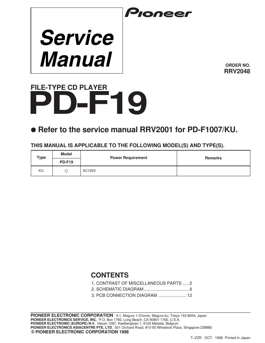
Service
Manual

FILE-TYPE CD PLAYER

Pioneer

ORDER NO.
RRV2048

PD-F19

0 Refer to the service manual RRV2001 for PD-F1007/KU.

THIS MANUAL IS APPLICABLE TO THE FOLLOWING MODEL(S) AND TYPE(S).

Model
Type Power Requirement Remarks
PD-F19
KU O AC120V

CONTENTS

1. CONTRAST OF MISCELLANEOUS PARTS ..... 2
2. SCHEMATIC DIAGRAM ..................................... e
3. PCB CONNECTION DIAGRAM ....................... 12

PIONEER ELECTRONIC CORPORATION 4-1, Meguro 1-Chome, MegurO-ku, Tokyo 153-8654, Japan
PIONEER ELECTRONICS SERVICE, INC. P.O. BOX1760, Long Beach, CA 90801-1760, U.S.A.

PIONEER ELECTRONIC (EUROPE) N.V. Haven 1087, Keetberglaan 1, 9120 MelseIe, Belgium

PIONEER ELECTRONICS ASIACENTRE PTE. LTD. 501 Orchard Road, #10-00 Wheelock Place, Singapore 238880

© PIONEER ELECTRONIC CORPORATION 1998

T-ZZR OCT. 1998 Printed in Japan

Page 2

PD-F19

1. CONTRAST OF MISCELLANEOUS PARTS

NOTES .'

0 Parts marked by NSP " are generally unavailable because they are not in our Master Spare Parts List.
0 The A mark found on some component parts indicates the importance of the safety factor of the part.
Therefore, when replacing, be sure to use parts of identical designation.
0 Reference Nos. indicate the pages and Nos. in the service manual for the base model.
0 When ordering resistors, first convert resistance values into codeform as shown in thefollowing examples.
Ex. 1 When there are 2 effective digits ( any digit apartfrom 0), such as 560 ohm and 47k ohm ( tolerance is shown by
J = 5%, andK =10%).


560 :2 -> 56 ><10-> 561 . RDl/4PU- J
47k a -> 47><103 -> 473 RBI/4PUE
o.5n->R5o .. RN2H®I@K
IQ->1R0... RSIPEEEK

such a. 11 high prec . ion metal film resistors).

.................................... RN1/4PC- .m F

Ex. 2 When there are 2? effective dig .
5.621(5) -> 562 X10-> 562]

l CONTRAST TABLE
PD-F19/KU and PD»F1007/KU are constructed the same except for the following:

Ref. _ _ Part No.
No. Mark Symbol and Descriptlon Remarks
PD-F1007/KU type PD-F19/KU type
ASSEMBLIES
A NSP MOTHER BOARD ASSY PWM2252 PWM2256
P5-1 MAIN BOARD ASSY PWZ3822 PWZ3826
KEY BOARD ASSY Not used PWZ3836 No.1
A NSP SUB BOARD ASSY PWX1576 PWX1579
P9-1 DISPLAY BOARD ASSY PWZ3839 PWZ3840
P5-2 POWER BOARD ASSY PWZ3852 PWZ3855
PACKING
P3-1 Styrol Protector F PHA1325 PHA1336
P3-2 Styrol Protector R PHA1326 PHA1337
P3-3 Packing Case PHG2316 PH62340
P3-6 Operating |nstructions(English) PRB1271 PFIB1276
P3-12 NSP Warranty Card ARY7023 ARY1026
EXTERIOR
P5-8 Bonnet Case PYY1255 PYY1263
P5-9 Rear Base PNA2424 PNA2457
P5-1 7 Hood PNW2793 PNW2872
Side Mole L Not used PNA1373 No.2
Side Mole R Not used PAN1374 No.3
Side Wood L Not used PMM1043 No.4
Side Wood R Not used PMM1044 No.5
Wood Collar Not used PNW1238 No.6
NSP Spacer Not used PNM1331 No.7
Screw Not used PBA1103 No.8
FRONT PANEL SECTION
P9-4 F-FC /3OV Connector PDD1189 PDD1188
P9-9 Name Plate PAM1776 PAN1376
P9-16 Operation Panel PNW2794 PNW2818

NOTE: ' The numbers in the remarks correspond to the numbers on the exploded diagram, Refer to "EXPLODED VIEWS".

- Fur ASSEMBLES, Refer to - CONTRAST OF PCB ASSEMBLIES" and "2.SCHEMATIC DIAGRAM".