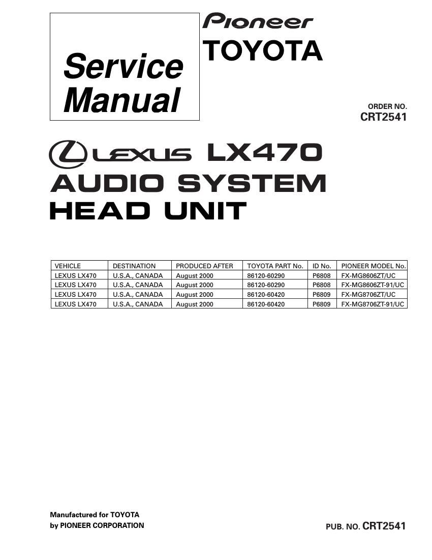
Pioneer fxmg 8606 zt 91 service manual

This is the 98 pages manual for pioneer fxmg 8606 zt 91 service manual.
Read or download the pdf for free. If you want to contribute, please mail your pdfs to info@audioservicemanuals.com.

Page: 1 / 98
left right
pioneer fxmg 8606 zt 91 service manual

Extracted text from pioneer fxmg 8606 zt 91 service manual (Ocr-read)


Page 2

FX-MGBSOSZT.MGBGOSZT-91.MGS7OGZT.MGB7OGZT-91

FX-MG8606ZT/UC FX-MG87OBZT/UC

(mm-VOL ) (I 2]) [(3 1)) ([5 6)) (saw use) (mm-m) ( MIR-VOL ) 1 z 3 a 5 6 sum use rum-n»:

E) {e- w-l Q a:- w; w
\, IND-MIIEDIW. IEIIfl'IfiDIMD
ID No.P6808 ID No.P6809
. This service manual should be used toqether with the following manualls):
Model No. Order No. Mech. Module Remarks
CX»631 CRT1640 2L Cassette Mech. ModulezMechDescription, Disassembly
CX»890 CRT2376 G1 CD Mech. ModulezCircuit Description, Mech.Description, Disassembly

. Dolby noise reduction manufactured under license from Dolby Laboratories Licensing Corporation.
"Dolby" and the double-D symbol are trademarks of Dolby Laboratories Licensing Corporation.

. Supplementary model is identical to the original except for the addition of following items.


Description Part No.
FX-MG86062T-91/UC FX-MG8707ZT-91/UC

Polyethylene Bag CEG1026 CEG1026

Carton CHA4143 CHA4143

Contain Box CHL4143 CHL4144

Protector(TOP) CHP2327 CHP2327

Protector(BO1TOM) CHP2328 CHP2328

CONTENTS

1. SAFETY INFORMATION ............................................ 4 7. GENERAL INFORMATION ....................................... 76
2. EXPLODED VIEWS AND PARTS LIST ....................... 5 7.1 DIAGNOSIS..........
3. BLOCK DIAGRAM AND SCHEMATIC DIAGRAM ...|2 7.1.1 TEST MODE
4. PCB CONNECTION DIAGRAM ................................ 36 7.1.2 DISASSEMBLY. ..
5. ELECTRICAL PARTS LIST .. 7.1.3 PCB LOCATIONS .....................................
6. ADJUSTMENT ................. 7.1.4 CONNECTOR FUNCTION DESCRIPTION ..

7.2 PARTS ................................................................
7.2.1 lC ..........

7.2.2 DISPLAY

7.3 EXPLANATION ...............................
7.3.1 SYSTEM BLOCK DIAGRAM

7.3.2 OPERATIONAL FLOW CHART ..

8. OPERATIONS AND SPECIFICATIONS ..................... 96