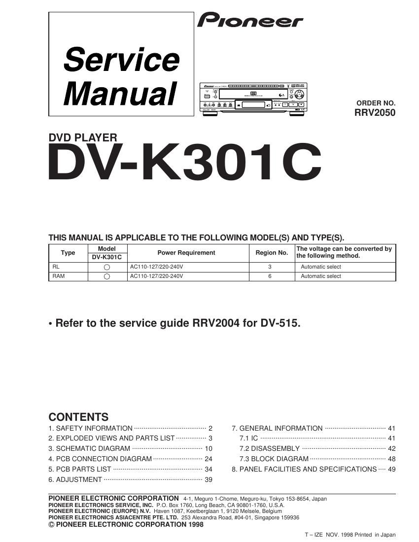
Pioneer dvk 301 c service manual

This is the 52 pages manual for pioneer dvk 301 c service manual.
Read or download the pdf for free. If you want to contribute, please mail your pdfs to info@audioservicemanuals.com.

Page: 1 / 52
left right
pioneer dvk 301 c service manual

Extracted text from pioneer dvk 301 c service manual (Ocr-read)


Page 1

Pioneer

Service
Manual

-EI :

ORDER NO.
RRV2050
DVD PLAYER
THIS MANUAL IS APPLICABLE TO THE FOLLOWING MODEL(S) AND TYPE(S).
Type Brigg: C Power Requirement Region No. Thheetzfigfifigcxieaeot:nverted by
RL 0 AC110-127/220-240V 3 Automatic select
RAM 0 AC110-127/220-240V 6 Automatic select

- Refer to the service guide RRV2004 for DV-515.

CONTENTS

1. SAFETY INFORMATION ...................................... 2 7_ GENERAL INFORMATION ................................ 41
2_ EXPLODED V|EWS AND PARTS LIST ..... 7.1 IC ............................ 41
3. SCHEMATIC DIAGRAM 7.2 DISASSEMBLY -- 42
4. PCB CONNECTION DIAGRAM 7.3 BLOCK DlAGRAM ----- 4s

5. PCB PARTS LIST
6. ADJUSTMENT --------

-- 34 8. PANEL FACILITIES AND SPECIFICATIONS 49

PIONEER ELECTRONIC CORPORATION 4-1, Meguro 1-Chome, Meguro-ku, Tokyo 153-8654, Japan
PIONEER ELECTRONICS SERVICE, INC. P.O. BOX1760, Long Beach, CA 90801-1760, U.S.A.

PIONEER ELECTRONIC (EUROPE) N.V. Haven 1087, Keetberglaan 1, 9120 Melsele, Belgium

PIONEER ELECTRONICS ASIACENTRE PTE. LTD. 253 Alexandra Road, #04-01, Singapore 159936

© PIONEER ELECTRONIC CORPORATION 1998
T - IZE NOV. 1998 Printed in Japan

Page 2

DV- K301 C

1. SAFETY INFORMATION

This service manual is intended for qualified service technicians ; it is not meant for the casual do-it-
yourselfer. Qualified technicians have the necessary test equipment and tools, and have been trained
to properly and safely repair complex products such as those covered by this manual.

Improperly performed repairs can adversely affect the safety and reliability of the product and may
void the warranty. If you are not qualified to perform the repair of this product properly and safely, you
should not risk trying to do so and refer the repair to a qualified service technician.

IMPORTANT
THIS PIONEER APPARATUS CONTAINS
LASER OF CLASS 1.
SERVICING OPERATlON OF THE APPARATUS
SHOULD BE DONE BY A SPEClALLY
INSTRUCTED PERSON.

7 LASER DlODE CHARACTERISTICS

FOR DVD: MAXIMUM OUTPUT POWER: 7 mw
WAVELENGTH : 650 nm

FOR CD: MAXIMUM OUTPUT POWER : 5mW
WAVELENGTH : 780 r 785 nm

-Additional Laser Caution

l. InSlde detection swrtch ($201 on the SMEB assy) and loading
status detection switch (89505 on the MOTOR assy) are detected
by the microprocessor (ICSOl in the DVDM assy).

- To permit the laser diode to oscillate, it is required to set the
Inside detection swttch for the inside position (3201 :ON) and to
set the loadingrstatus detecllon switch for the clamp position (the
center terminal of 89503 is shorted to +5V). The 650 nm laser
diode for DVD oscillation will continue lf pin 19 of IC101 is shorted
Io +5V (fault condition) in the DVDM assy.

The 780 nm laser diode for CD oscillates if pm 20 of |C101 is
shorted to +5V in the DVDM assy.

In the test mode * ,Ihe laser diode oscillates when microprocesr
sor detects a PLAY signal, or when the PLAY key is pressed
(St 32 ON in the FLKB assy), with the above requirements satlsV
lied.

2. When the cover is open, close viewrng through the objective lens
with the naked eye thI cause exposure to the laser beam.

* : Refer to the service guide RRV2004.