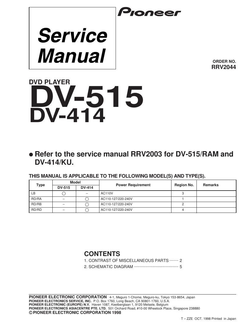
Pioneer dv 414 service manual

This is the 5 pages manual for pioneer dv 414 service manual.
Read or download the pdf for free. If you want to contribute, please mail your pdfs to info@audioservicemanuals.com.

Page: 1 / 5
left right
pioneer dv 414 service manual

Extracted text from pioneer dv 414 service manual (Ocr-read)


Page 1

DV-515, DV-414 2 1. CONTRAST OF MISCELLANEOUS PARTS PCB ASSEMBLIES P8 - 6 POWER SUPPLY ASSY VWR1306 VWR1305*1 PACKING P4 - 1 AC Power Cord ADG7017 ADG7003 P4 - 3 Operating Instructions VRC1079 Not used (Simp. Chinese Language) P4 - 4 NSP Warranty Card ARY7028 Not used P4 - 8 Operating Instructions (English) VRB1204 Not used P4 - 8 Operating Instructions Not used VRC1078 (Trad. Chinese Language) P4 -11 Protector A Not used VHB1060 P4 -12 Protector B Not used VHB1061 P4 -13 Packing Case VHG1774 VHG1777 P4 -17 Pad F VHA1220 Not used P4 -18 Pad R VHA1221 Not used BOTTOM VIEW SECTION P8 -13 Rear Panel VNA2035 VNA2003 P8 -22 NSP Housing Assy VKP2189 Not used Ref. No.Remarks RAM type LB typePart No. Mark Symbol and Description 7 CONTRAST TABLE for DV-515 DV-515/LB and DV-515/RAM are constructed the same except for the following: NOTES :ÖParts marked by Ò NSP Ó are generally unavailable because they are not in our Master Spare Parts List. ÖThe mark found on some component parts indicates the importance of the safety factor of the part. Therefore, when replacing, be sure to use parts of identical designation. ÖReference Nos. indicate the pages and Nos. in the service manual for the base model. ÖWhen ordering resistors, first convert resistance values into code form as shown in the following examples. Ex. 1 When there are 2 effective digits (any digit apart from 0), such as 560 ohm and 47k ohm (tolerance is shown by J = 5%, and K = 10%). 560 W = 56 ´ 10 1 = 561 ...................................................RD1/4PU 5 6 1 J 47k W = 47 ´ 10 3 = 473 ..................................................RD1/4PU 4 7 3 J 0.5 W = R50 ......................................................................RN2H å 5 0 K 1 W = 1R0 ......................................................................... RS1P 1 å 0 K Ex. 2 When there are 3 effective digits (such as in high precision metal film resistors). 5.62k W = 562 ´ 10 1 = 5621...........................................RN1/4PC 5 6 2 1 F *1 This assembly is used for DV-414/KU. Refer to the service manual RRV2003.

Page 2

DV-515, DV-414 3 7 CONTRAST TABLE for DV-414 DV-414/RD/RA, RD/RB, RD/RD and KU are constructed the same except for the following: PCB ASSEMBLIES NSP FLKB ASSY VWM1847 VWM1851 VWM1851 VWM1851 P6 -15 FLKY ASSY VWG1971 VWG1974 VWG1974 VWG1974*1 P8 -12 AVJB ASSY VWV1615 VWV1642 VWV1642 VWV1642*1 P8 - 6 POWER SUPPLY ASSY VWR1305 VWR1306 VWR1306 VWR1306*2 PACKING P4 - 1 AC Power Cord ADG7021 ADG7003 ADG7003 ADG7003 P4 - 3 Operating Instructions Not used Not used Not used VRD1089 (Spanish/Portuguese) P4 - 4 NSP Warranty Card ARY7023 ARY7025 Not used Not used P4 -13 Packing Case VHG1756 VHG1793 VHG1793 VHG1793 Label (Region) Not used VRW1708 VRW1701 VRW1705*3, No.1 EXTERIOR SECTION P5 -17 65 Label ORW1069 Not used Not used Not used FRONT PANEL SECTION P6 - 1 Front Panel VNK4315 VNK4386 VNK4386 VNK4386 BOTTOM VIEW SECTION P8 -13 Rear Panel VNA1990 VNA2016 VNA2016 VNA2016 P8 -22 NSP Housing Assy Not used VKP2189 VKP2189 VKP2189 Label (Region) Not used VRW1709 VRW1700 VRW1704*3, No.2 Remarks Part No. KU type RD/RA type RD/RB type RD/RD type Ref. No.MarkSymbol and Description *1 Refer to Ò CONTRAST OF PCB ASSEMBLIES Ó. *2 This assembly is used for DV-515/RL. Refer to the service manual RRV2003. *3 The numbers in the remarks column correspond to the numbers on the Ò EXPLODED VIEWS Ó . 7 EXPLODED VIEWS Protector B Protector A Packing CaseNo.1 No.1 Rear Panel No.2 Ö BOTTOM VIEW SECTION Ö PACKING SECTION