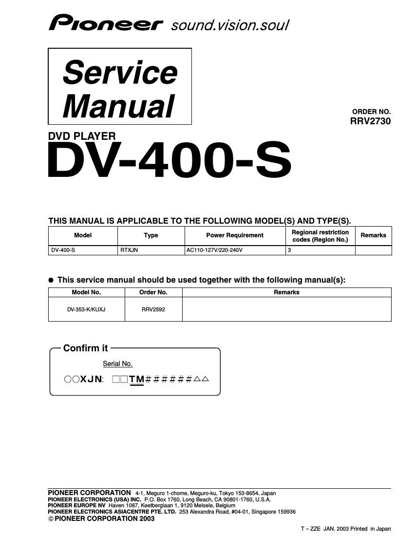
Pioneer dv 400 s service manual

This is the 11 pages manual for pioneer dv 400 s service manual.
Read or download the pdf for free. If you want to contribute, please mail your pdfs to info@audioservicemanuals.com.

Page: 1 / 11
left right
pioneer dv 400 s service manual

Extracted text from pioneer dv 400 s service manual (Ocr-read)


Page 1

2 1 23 4 1234 C D F A B E DV-400-S 1. CONTRAST OF MISCELLANEOUS PARTS 7 CONTRAST TABLE DV-400-S/RTXJN and DV-353-K/KUXJ are constructed the same except for the following: PCB ASSEMBLIES P11 - 1 NSP LOAB Assy VWG2346 VWG2279 P9 - 3 FJMB Assy VWS1515 VWS1553 P9 - 7>POWER SUPPLY Unit VWR1351 VWR1352 (or VWR1353) (or VWR1354) (or VWR1363) (or VWR1364) PACKING P7 - 1>Power Cable ADG7022 ADG1154 P7 - 2 NSP Warranty Card ARY7057 Not used P7 - 5 Operating Instructions (English) VRB1285 Not used P7 - 9 Pad L VHA1295 VHA1336 P7 -10 Pad R VHA1296 VHA1337 P7 -11 Paper Board VHC1088 VHC1097 P7 -12 Packing Case VHG2237 VHG2363 P7 -13 Seat Z23-007 VHL1068 Operating Instructions (Thai) Not used VRC1187 Ref. No.Remarks DV-353-K/KUXJ DV-400-S/RTXJN Part No. Mark Symbol and Description Parts marked by "NSP" are generally unavailable because they are not in our Master Spare Parts List. The mark found on some component parts indicates the importance of the safety factor of the part. Therefore, when replacing, be sure to use parts of identical designation. Screws adjacent to mark on product are used for disassembly. For the applying amount of lubricants or glue, follow the instructions in this manual. (In the case of no amount instructions, apply as you think it appropriate.) NOTES: When ordering resistors, first convert resistance values into code form as shown in the following examples. Ex.1 When there are 2 effective digits (any digit apart from 0), such as 560 ohm and 47k ohm (tolerance is shown by J=5%, and K=10%). Ex.2 When there are 3 effective digits (such as in high precision metal film resistors). 561 473 R50 1R0 5621 560 -„¦ 47k -„¦ 0.5 -„¦ 1 -„¦ RD1/4PU J RD1/4PU J RN2H K RS1P K 56 x 10 1 47 x 10 3 R50 1R0561 473 5.62k -„¦ RN1/4PC F 562 x 10 1 5621

Page 2

3 5 678 5 67 8 C D F A B E DV-400-S -The numbers in the remarks column correspond to the numbers on the EXPLODED VIEWS. -For PCB assemblies, Refer to CONTRAST OF PCB ASSEMBLIES, PCB PARTS LIST, 2. SCHEMATIC DIAGRAM and 3. PCB CONNECTION DIAGRAM. EXTERIOR SECTION P9 -12 NSP Base Chassis VNA2409 VNA2501 P9 -13 Rear Panel VNA2421 VNA2600 P9 -15 DVD V Plate VAM1121 Not used P9 -18 Tray Panel VNK4952 VNK5275 P9 -19 Front Panel Assy VXA2486 Not used P9 -20 Pioneer Badge XAM3006 Not used P9 -21 NSP Energy Star Label AAX7876 Not used P9 -25 Screw BCZ40P060FZK BCZ40P060FNI P9 -26 Bonnet Case S VXX2821 VXX2822 Display Panel A Not used VAH1406 No. 1 Display Panel B Not used VAH1401 No. 2 Display Panel C Not used VAH1407 No. 3 Door Spring Not used VBH1341 No. 4 Door Cusion Not used VEC2312 No. 5 Main Key Not used VNK5272 No. 6 Sub Key Not used VNK5273 No. 7 Door Not used VNK5274 No. 8 Door Shaft Not used VNK5276 No. 9 Shaft Holder Not used VNK5277 No. 10 Front Panel Not used VNK5271 No. 11 Screw Not used BPZ26P060FMC No. 12 Caution Label Not used VRW1872 for Bonnet LOADING MECHANISM ASSY P11 -23 Tray VNL1920 VNL1950 Ref. No.Remarks DV-353-K/KUXJ DV-400-S/RTXJN Part No. Mark Symbol and Description 7 CONTRAST OF PCB ASSEMBLIES F B FJMB ASSY VWS1553 and VWS1515 are constructed the same except for the following: IC603 VYW2031 VYW2072 R27 RS1/16S333J RS1/16S682J R28 RS1/16S562J RS1/16S272J R37 Not used RS1/16S0R0J Connected to the No.27 pin of IC11. R38 RS1/16S0R0J Not used Mark Symbol and DescriptionPart No. VWS1515 VWS1553Remarks LOAB ASSY Although VWG2279 and VWG2346 are different in part number, they have the same service parts.