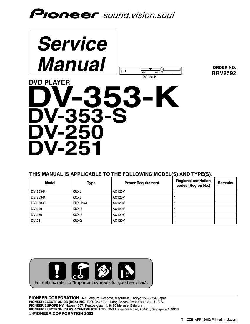
Pioneer dv 250 service manual

This is the 86 pages manual for pioneer dv 250 service manual.
Read or download the pdf for free. If you want to contribute, please mail your pdfs to info@audioservicemanuals.com.

Page: 1 / 86
left right
pioneer dv 250 service manual

Extracted text from pioneer dv 250 service manual (Ocr-read)


Page 1

4 DV-353-K 1. SPECIFICATIONS ................................................................................................................................................. 5 2. EXPLODED VIEWS AND PARTS LIST ............................................................................................................... 6 2.1 PACKING ........................................................................................................................................................ 6 2.2 EXTERIOR SECTION ..................................................................................................................................... 8 2.3 LOADING MECHANISM ASSY ................................................................................................................... 10 2.4 TRAVERSE MECHANISM ASSY-S ............................................................................................................ 14 3. BLOCK DIAGRAM AND SCHEMATIC DIAGRAM ............................................................................................ 16 3.1 BLOCK DIAGRAM ....................................................................................................................................... 16 3.1.1 SIGNAL ROUTE ........................................................................................................................................ 16 3.1.2 POWER SUPPLY BLOCK ........................................................................................................................ 18 3.1.3 WAVEFORMS ........................................................................................................................................... 19 3.2 LOAB ASSY and OVERALL WIRING DIAGRAM ........................................................................................20 3.3 FJMB ASSY 1/5 [FRONT END BLOCK] ...................................................................................................... 22 3.4 FJMB ASSY 2/5 [BACK END BLOCK] ........................................................................................................ 24 3.5 FJMB ASSY 3/5 [AUDIO BLOCK] ............................................................................................................... 26 3.6 FJMB ASSY 4/5 [VIDEO BLOCK] ................................................................................................................ 28 3.7 FJMB ASSY 5/5 [FL CONTROL BLOCK] .................................................................................................... 30 3.8 IRKY and PSWB ASSYS ............................................................................................................................. 32 3.9 POWER SUPPLY UNIT (VWR1351) ........................................................................................................... 34 3.10 POWER SUPPLY UNIT (VWR1353) ......................................................................................................... 35 4. PCB CONNECTION DIAGRAM ......................................................................................................................... 37 4.1 LOAB ASSY ................................................................................................................................................. 37 4.2 FJMB ASSY .................................................................................................................................................. 38 4.3 IRKY and PSWB ASSYS ............................................................................................................................. 42 4.4 POWER SUPPLY UNIT (VWR1351) ........................................................................................................... 43 4.5 POWER SUPPLY UNIT (VWR1353) ........................................................................................................... 44 5. PCB PARTS LIST ............................................................................................................................................... 45 6. ADJUSTMENT .................................................................................................................................................... 48 6.1 ADJUSTMENT ITEMS AND LOCATION ..................................................................................................... 48 6.2 JIGS AND MEASURING INSTRUMENTS ................................................................................................... 48 6.3 NECESSARY ADJUSTMENT POINTS ....................................................................................................... 49 6.4 TEST MODE ................................................................................................................................................. 50 6.5 MECHANISM ADJUSTMENT ...................................................................................................................... 51 7. GENERAL INFORMATION ................................................................................................................................ 54 7.1 DIAGNOSIS .................................................................................................................................................. 54 7.1.1 TEST MODE .............................................................................................................................................. 54 7.1.2 DISPLAY OF THE MECHANISM ERROR HISTORY .............................................................................. 60 7.1.3 TEST POINTS LOCATION & WAVEFORMS ........................................................................................... 64 7.1.4 TROUBLE SHOOTING ............................................................................................................................. 68 7.1.5 SEQUENCE AFTER THE POWER ON .................................................................................................... 70 7.1.6 DISASSEMBLY ......................................................................................................................................... 71 7.2 IC .................................................................................................................................................................. 76 7.3 CLEANING ................................................................................................................................................... 94 8. PANEL FACILITIES ............................................................................................................................................ 95 CONTENTS

Page 2

5 DV-353-K General System............................DVD-Video, Video CD, CD and MP3 files Power requirements..................AC 120 V, 60 Hz Output level..............................Y: 1.0Vp-p (75 -„¦) P B, P R: 0.7 Vp-p (75 -„¦) Jacks...................................................RCA jacks Power consumption.....................................13 W Power consumption (standby) ........................0.3 W Weight.........................................2.4 kg (5lb 5oz) Dimensions DV-353.............420 (W) x 55 (H) x 278 (D) mm (16 9/16 (W) x 2 3/16 (H) x 10 15/16 (D) in.) DV-250/251......420 (W) x 55 (H) x 276 (D) mm (16 9/16 (W) x 2 3/16 (H) x 10 14/16 (D) in.) Operating temperature.................+5°C to +35°C (+36°F to +96°F) Operating humidity.............................5% to 85% (no condensation) S-Video output Y (luminance) - Output level...........1 Vp-p (75 -„¦) C (color) - Output level............286 mVp-p (75 -„¦) Jack.................................................S-Video jack Video output Component Video output (Y, P B, P R) Output level....................................1 Vp-p (75 -„¦) Jack......................................................RCA jack Audio output (1 stereo pair) Output level..........................During audio output 200 mVrms (1 kHz, -“20 dB) Number of channels...........................................2 Jacks.....................................................RCA jack Digital audio characteristics Frequency response....................4 Hz to 44 kHz (DVD fs: 96 kHz) S/N ratio...................................................118 dB Dynamic range.........................................101 dB Total harmonic distortion......................0.0016 % Wow and flutter.................Limit of measurement (0.001% W. PEAK) or lower Digital output Optical digital output...............Optical digital jack Coaxial digital output............................RCA jack Accessories Audio/video cable...............................................1 Power cable....................................................... 1 Remote control...................................................1 AA/R6P dry cell batteries...................................2 Operating Instructions........................................1 Warranty card.................................................... 1 -The specifications and design of this product are subject to change without notice, due to improvement. - Manufactured under license from Dolby Laboratories. Dolby and the double-D symbol are trademarks of Dolby Laboratories. - DTS is a registered trademark of Digital Theater Systems, Inc. - TruSurround and the ® symbol are trademarks of SRS Labs, Inc. TruSurround technology is incorporated under license from SRS Labs, Inc. Audio/Video Cable (L=1.5m): XDE3049 AA/R6P Dry Cell Batteries Power Cable : ADG7022 Remote Control : VXX2800 Accessories White Red Yellow 0 123 456 789 CLEAR ENTERANGLE AUDIO TOP MENU SETUP SUBTITLE PLAY MODE SURROUND ZOOM DISPLAY MENU RETURN ENTER STANDBY/ONOPEN/CLOSE 4/eE/ 13 ¡ ¢ 8 7 0 1. SPECIFICATIONS