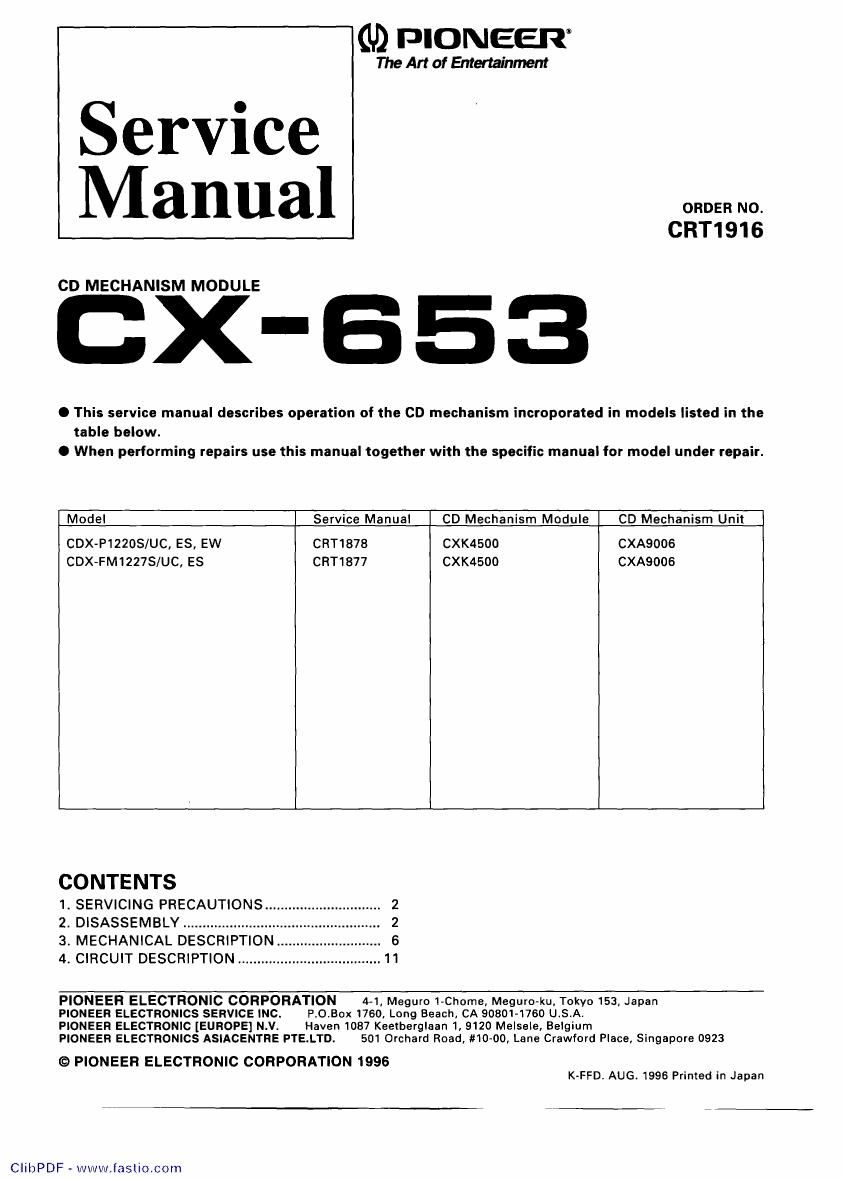
Pioneer cx 653 service manual

This is the 24 pages manual for pioneer cx 653 service manual.
Read or download the pdf for free. If you want to contribute, please mail your pdfs to info@audioservicemanuals.com.

Page: 1 / 24
left right
pioneer cx 653 service manual

Extracted text from pioneer cx 653 service manual (Ocr-read)


Page 1

(U) PIONEER

The Art of Entertainment

Service
Manual

CRT1916

CD MECHANISM MODULE

X-653

O This service manual describes operation of the CD mechanism incroporated in models lisled in the
table below.

0 When performing repairs use this manual together with the specific manual for model under repair.

Model Service Manual CD Mechanism Module CD Mechanism Unit

CDX-P12ZOS/UC, ES, EW CRT1878 CXK4500 CXAQOOB
CDX-FM1227S/UC, ES CRT18I7 CXK4500 CXA9006

CONTENTS
1. SERVICING PRECAUTIONS ......
2. DISASSEMBLY .......................
3. MECHANICAL DESCRIPTION
4. CIRCUIT DESCRIPTION .............

.umNN

PIONEER ELECTRONIC CORPORATION 4-1, Meguro 1-Chorne, Meguro-ku. Tokyo 153, Japan

PIONEER ELECTRONICS SERVICE INC. P.O.BOX 1760, Long Beach, CA 90301-1750 UIS.A.

PIONEER ELECTRONIC [EUROPE] N.V. Haven 1087 Keetberglaan 1, 9120 Melsele, Belgium

PIONEER ELECTRONICS ASIACENTRE PTE.LTD. 501 Orchard Road. #10-00, Lane Crawford Place, Singapore 0923

© PIONEER ELECTRONIC CORPORATION 1996
K»FFD. AUG. 1996 Printed in Japan

CIibPDF - www.faslio.com

Page 2

(BX-653

1. SERVICING PRECAUTIONS

1)Do not carry out any work holding the upper sur-
face of the magazine insert slot on the mechanism,
marked by an arrow, since it deforms easily.

2)When the Stage Mechanism is positioned below the
11th level, it protrudes below the chassis. Do not
leave it in this position as it may become damaged.


CD Mechanism Module

2. DISASSEMBLY

. Removing the Pick-up Unit

1. Attach the Short Pin onto the Flexible P.C.Board of
the Pick-up Unit.lFig.2)

2. Remove the Flexible P.C.Board from the
connector.(Fig.2)

3. Remove the Torsion Spring which is pressed
against the leading edge of the Feed Screw.(Fig.3)

4. Remove the Screw and Pulley Cover.(Fig.3)

5. Remove the Belt and the Pickup Unit with the Feed
Screw still attached.(Fig.3)

6. Lift the Tabs of the rack section of the Holder and re»
move the Feed Screw. While doing so. be careful not
to lose the Bearings on the ends of the Feed
Screw.(Fig.3)


Sensor Lever

O Removing the CD Core Unit (Fig.2) Pick-up Unit
1.After procedures 1 and 2 for removing the Pick-up Fig.2
Unit, remove the connector.
2. Remove the Elevation Motor Assy lead wires
marked with an arrow which are soldered onto the
CD Core Unit. Screw
3. Remove screw (A), screw (8) and screws (C)(2
screws), then remove the CD Core Unit.

Pulley Cover


Bearing Feed

. Precautions for Installing the CD Core Unit

If the sensor lever of the Linear Position Sensor
(Slide Volume: VR801) of the CD Core Unit is not in-
serted properly in the U-shaped Groove the elevation
operation may not function properly. When installing
the CD Core Unit in the CD Mechanism Unit insert the
Linear Position Sensor (Slide Volume: VR801) se- Torsion Spring
curely in the U-shaped Groove.

C Removing the Carriage Motor Assy (Fig.3) Bearing

1. After procedures 3 and 4 for removing the Pick-up
Unit, remove the Belt, and the Carriage Motor /CarnageMotorAssy

Assy. Fig.3

CIibPDF - www.fastio.com