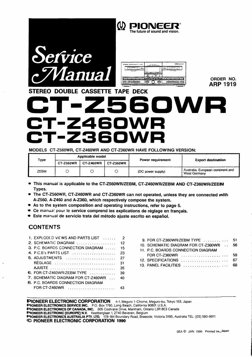
Pioneer ctz 460 wr service manual

This is the 56 pages manual for pioneer ctz 460 wr service manual.
Read or download the pdf for free. If you want to contribute, please mail your pdfs to info@audioservicemanuals.com.

Page: 1 / 56
left right
pioneer ctz 460 wr service manual

Extracted text from pioneer ctz 460 wr service manual (Ocr-read)


Page 1

GD PIONEERQ

The future of sound and vision.

Scfiice
Wanna]

STEREO DOUBLE CASSETTE TAPE DECK

CT-ZESDWFI

CT-Z4BDWFI
CT-Z3BDWFI

MODELS CT-2560WR, CT-Z460WR AND CT-2360WR HAVE FOLLOWING VERSION:

Applicable model
Type Power requirement Expon destination

CT-ZSGDWR CT-ZMSOWR CT-ZSBDWR

ORDER No.
ARP 1 919

ZEBM O O 0 (DC power supply) gigngggpean min-lent and

o This manual is applicable to the CT-ZSGOWR/ZEBM, CT-Z460WR/ZEBM AND CT-Zasown/ZEBM
Types.

0 The CT ~2560WR, CT-Z460WR and CT-2360WR can not operated, unless they are connected with
A-2560. A-2460 and A-2360, which respectively compose the system.

0 As to the system composition and operating instructions, refer to page 5.

0 Ce manual pour Ie service comprend les explications de re'glage en frangais.

0 Este manual de servicio trata del método aiuste escrito en espafiol.

CONTENTS

;:52:33:1ngme.3667???.;::::: 9. WWW ----------- 51

3 P C BOARDS CONNECTION DIAGRAM 15 10 SCHEMATIC DIAGRAM FOR CT-ZSGOWR I . 56

' ' ~ _ """ 11 PC. BOARDS CONNECTION DIAGRAM

4. PCB S PARTS LIST .................... 23

5- ADJUSTMENTS ..................... 27 FOR CT-ZSGOWR ..................... 59
HEGLAGE 31 IZSPECIHCATIONS """"""""""""" 67
AJUSTE ............................ 35 13. PANEL FACILITIES .................... 68

6 FOR CT-Z460WR/ZEBM TYPE ............ 39

7. SCHEMATIC DIAGRAM FOR CT-Z460WR . I . 40

8. PVC, BOARDS CONNECTION DIAGRAM
FOR CT-Z460WR ...................... 43

FIONEER ELECTRONIC CORPORATION 4-1, Meguro 1«Chome. Meguro-ku, Tokyo 153, Japan

PIONEER ELECTRONICS SERVICE INC. PO, Box 1760. Long Beach. California 90801 USA.

PIONEER ELECTRONICS OF CANADA, INC. 505 Cochrane Drive, Markham, Ontario L3R 6E3 Canada

PIONEER ELECTRONIC [EUROPE] N.V. Keetberglaan 1, 2740 Beveren, Belgium

PIONEER ELECTRONICS AUSTRALIA PTY. LTD. 178484 Boundary Road, Braeside, Victoria 3195 Australia TEL: [03] 580-9911

© PIONEER ELECTRONIC CORPORATION 1990

SEA © JAN 1990 Primed inJapa"

Page 2

CT-ZSBOWR

1. EXPLODED VIEWS AND PARTS LIST

NOTES:
0 Paris without part number cannot be supplied.

0 The A mark found on some component pans indicates the importance of the safety
factor of the part. Therefore, when replacing, be sure to use pans of identical designa-

tion.

0 Parts marked by Q are not always kept in stock. Their delivery time may be longer
than usual or they may be unavailable.

1.1 Exterior and Packing
Mark No. Descrimion

SlPQNr

11.
12.
13.
14.
15.

16.
17.
18.
19.
20.

21 .
22.
23.
24.
25.

26.
27.
28.
29.
30.

31 .
32.
33.
34.
35.

86.
37.
38.
39.
40.

Parts No.
Name plate
Foot ass'ys
Camjon card (NOTE') ARH1047
Door panel (L) Ass'y RXX1257
Screw BBZZSPOSOFMC
Screw BBZsOPOGOFCC
Screw BBZSOPOSOFZK
Screw BBZSOP120FZK
Screw lBZsOP1 50FCU
PCB Spacer
Knob (MODE) RAC1380
Knob (EJECT L) RAC1463
Knob (EJECT R) RAcusA
Knob (PLAY) RAC1465
Knob (REC) RAC1466
Knob (COPY) RAC1467
Knob (SLIDE) RACMBQ
Knob (VR) RAC1470
Filler (FL) RAH1 51 2
Door panel (L)
Door Panel (R) RAH1 579
Front Panel RAH1674
Spring (Door L) RBH1203
Spring (Door R) RBH1204
Spring RBK1 004
Binder REC-371
Spacer (PVC)
Damper assy REC1 01 3
lndicaling panel REE-1 1 3
Pad (F) RHA1036
Pad (Fl) RHA1037
Polyslylene cover RHC1 002
Packing case RHG1 157
Connector assy 5P RKP1323
Arrn color
Door lens (L) RLP1 030
Door lens (R) RLPioa1

Mark No. De§§r§2fion Pans No.
41. FL Lens RLP1033
42. Bonnet RXX1225
43. Rear panel
44. Main shassis
45. Mechanism mount

plate
46. Eject arm (L)
47. Eject arm (Fl)
48. Mechanism shield
plate
49. Card clamper RNH-184
50. Door pocket RNT1008
51. --- -
52. F001
53. Cushion
s4. Fool ass'y RXA1276
55. Knob assy (ASES) RXA135
56. Mechanism uniKDeck l)
57. Mechanism unil (Deck ll)
58. Screw BCZZBFDSOFMC
59. Connector assy 15F RKP1318
60. ~------
61. HX Assy
62. -
63.
64.
55.
66. , VR Assy
67. Transistor A Assy
68. Transistor B Assy
69. Main Assy
70. ~------
71. Operation 1 Assy
72. Operalion 2 Assy
73. Display Assy
74. Connection Ass'y