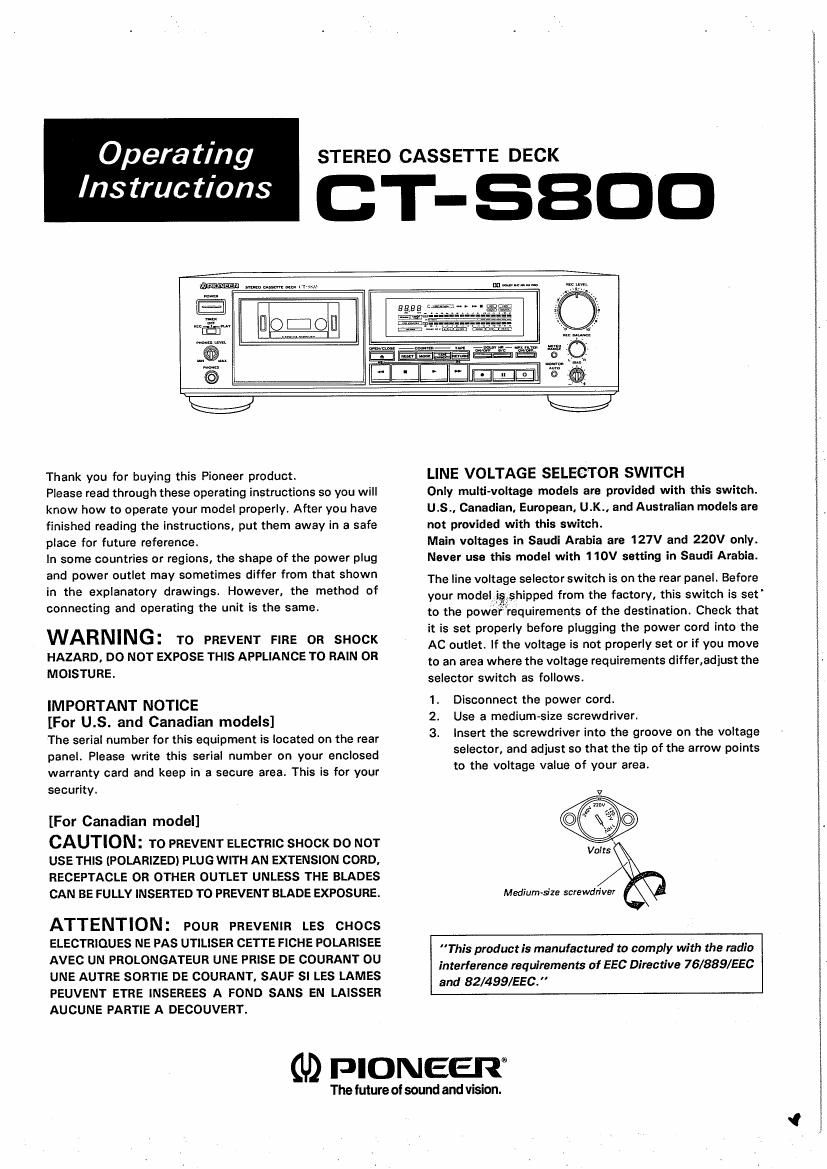
Pioneer cts 800 owners manual

This is the 20 pages manual for pioneer cts 800 owners manual.
Read or download the pdf for free. If you want to contribute, please mail your pdfs to info@audioservicemanuals.com.

Page: 1 / 20
left right
pioneer cts 800 owners manual

Extracted text from pioneer cts 800 owners manual (Ocr-read)


Page 1

Opera ting

Ins truc tions

STEREO CASSETTE DECK

CT-SBDD


.. or

-& o
ITIlrfi lTu-ITJ a, .

Thank you for buying this Pioneer product.

Please read through these operating instructions so you will
know how to operate your model properly. After you have
finished reading the instructions, put them away in a safe
place for future reference.

In some countries or regions, the shape of the power plug
and power outlet may sometimes differ from that shown
in the explanatory drawings. However, the method of
connecting and operating the unit is the same.

WARNING: TO PREVENT FIRE 0R SHOCK

HAZARD, DO NOT EXPOSE THIS APPLIANCE TO RAIN OR
MOISTURE.

IMPORTANT NOTICE

[For U.S. and Canadian models]

The serial number for this equipment is located on the rear
panel. Please write this serial number on your enclosed
warranty card and keep in a secure area. This is for your
security.

[For Canadian model]

CAUTION: To PREVENT ELECTRIC SHOCK DO NOT
USE THIS (POLARIZED) PLUG WITH AN EXTENSION CORD.
RECEPTACLE OR OTHER OUTLET UNLESS THE BLADES
CAN BE FULLY INSERTED TO PREVENT BLADE EXPOSURE.

ATTENTION: POUR PREVENIR LEs cnocs
ELECTRIQUES NE PAS UTILISER CETTE FICHE POLARISEE
AVEc UN PROLONGATEUR UNE PRISE DE COURANT ou
UNE AUTRE SORTIE DE COURANT, SAUF sI LEs LAMEs
PEUVENT ETRE INSEREES A POND sANs EN LAISSER
AUCUNE PARTIE A DECOUVERT.

LINE VOLTAGE SELECTOR SWITCH

Only multi-Voltage models are provided with this switch.
U.S., Canadian, European, U.K., and Australian models are
not provided with this switch.

Main voltages in Saudi Arabia are 127V and 220V only.
Never use this model with 1 10V setting in Saudi Arabia.

The line voltage selector switch is on the rear panel. Before

your model igishipped from the factory, this switch is set'
to the powerrequirements of the destination. Check that

it is set properly before plugging the power cord into the

AC outlet. If the voltage is not properly set or if you move

to an area where the voltage requirements differ,adjust the

selector switch as follows.

1. Disconnect the power cord.

2. Use a medium-size screwdriver.

3. Insert the screwdriver into the groove on the voltage
selector, and adjust so that the tip of the arrow points
to the voltage value of your area.

Volts

Medium-5'19 screwdriver

"This praductis manufactured to comply with the radio
interference requirements of EEG Directive 76/889/EEC
and 82/499/EEC."

(U) PIONEER

The future of sound and vision.

Page 2

IMPORTANT 1

The lightning flash with arrowhead, within an equip
lateral triangle. is intended to alert the user of the
presence OI uninsulated "dangerous voltage within
the Product's enclosure that may be oi sufficient
magnitude to constitute a risk of electric shock to
persons.

CAUTION

RISK OF ELECTRIC SHOCK
DO NOT OPEN

CAUTION:

TO PREVENT THE RISK OF ELECTRIC SHOCK,
DO NOT REMOVE COVER (OR BACK). NO
USER-SERVICEABLE PARTS INSIDE. REFER
SERVICING TO QUALIFIED SERVICE
PERSONNEL.

The exclamation point within an equilateral triangle is
intended to alert the user of the presence of important
operaling and maintenance (servicing) instructions in
the literature accompanying the appliance.

IM PORTANT 2

It the apparatus is titted with Ac mains power out.
let(s), see REAR PANEL FACILITIES lor convenient
connection or additional Hi-Fi component(s). Make
all connections to the Ac outlet(s) and the signal
terminals rirst. Connect the plug to the wall socket
lest make sure that the power switch is on,

FOR USE IN THE UNITED
KINGDOM

The wires in this mains lead are coloured in accor»
dance with the iollawing coda:

Blue: Neuual

Brown: Live

As the colours DI the wires in the mains lead of this
apparatus may not correspond with the coloured
marking identifying the terminals in your plug proceed
as Iollows:

The wire which is coloured blue must be connected to
the terminal which is marked with the letter N or
coloured black.

The wire which is coloured brown must be connected
to the terminal which is marked with the letter L or
coloured red.

Equipment sold in the U.Ko is not supplied with
a power plug.

READ INSTRUCTIONS 7 All the safety and
operating instructions should be read before the
appliance is operated.

RETAIN INSTRUCTIONS 7 The operating instruc-
tions should be retained for future reterence.
HEED WARNING -All warnings on the appliance
and in the operating instructions should he

adhered to.

FOLLOW INSTRUCTIONS -Ali operating and use
instructions should he followed,

WATER AND MOISTURE - The appliance should
not be used near water - for example, near a
bathtub, washbowl, kitchen sink laundry tub, in a
wet basement. or near a swimming pool, etc.

LOCATION - The appliance should be installed in a
stable locatiant

WALL OR CEILING MOUNTING 7 The appliance
should not be mounted to a wall Or ceiling.

VENTILATION 7The appliance should be situated
so that its location or position does not interfere
with its proper ventilation. For example, the ap-
pliance should not be situated on a bed, sore. rug,
or similar surface that may block the ventilation
openings; or, placed in a built-in installation. such
as a bookcase or cabinet that may impede the
flow or air through the ventiladon Openings

HEAT- The appliance should be situated away from
heat sources such as radiators. heat nagisters,
stoves, or other appliances (including ampliiiers)
that pfoduce heat.

POWER SOURCES-The appliance .should be
connected to a power supply only oi the type
described in the operating instructions or as
marked on the appliance,

POWER-CORD PROTECTION - Power-supply
cards should be routed so that they are not likely
to be walked on or pinched by items placed upon
or against them. paying particular attention to
cords at plugs. convenience receptacles and the
point where they exit from the appliance.

POLARIZATION - It Your purchased product is
provided with a polarized power plug. please read
the lollowing instructions. This product is
equipped a polarized alternating Current line
plug (a plug having one blade wider than the
other). This plug will fit into the power outlet only
one way. This is a satety iesture. Ir you are unable
to insert the plug fully into the OuIIeL try reversing
the plug. II the plug should still tail to fit, Contact
your electrician to repiace your Obsolete outlet.
Do not defeat the safety purpose of the polarized
plug.

CLEANING -- The appliance should he cleaned only
with a polishing cloth or a soft dry Cloth. Never
clean with furniture wax, benline. insecticides or
other volatile Iiguids since they may corrode the
cabinet.

POWER LINES - An outdoor antenna should be

SAFETY INSTRUCTIONS

located away rrom power lines.

NONUSE PERIODS7 The power cord of the
appliance should be unplugged (tom the outlet
when left unused tor a long period of time.

OBJECT AND LIQUID ENTRY-Care should be
taken so that objects do not fall and liquids are
not spilled into the enclosure through openings.

DAMAGE REQUIRING SERVICE7 The appliance
should be serviced by a Pioneer authorized ser
vice center or qualilied service personnel when:

a The power-supply cord or the plug has been
damaged; or

o oorects have rallen, or liquid has been spilled into
the appliance: or

o The avplience has been exposed to rai or

3 The appliance does not appear to operate nor-
mally or exhibits a marked Change in perior-
mance; or

o The appliance has been dropped; or the enclosure
damaged.

SERVICING-The user should not attempt to
service the appliance beyond that described in the
operating instructions, For all other servicing,
Contact the nearest Pioneer authorized service
center.

SERVICE
ENTRANCE
CONDUCTOHS

GROUND
GROUND WIRE Lb


SERVICE ENTRANCE
EQUIPMENT

POWER SERVICE
GRDUNDING ELECTRODE SYSTEM
(cg interior motor water pipe)

in
I h; CLAMPS

BONDING II

JUMPER ('1 II

EreA ,.
Ii NEC SECTION

ANTENNA
_'LEAD~IN WIRE
__ To EXTERNAL ANTENNA

GROUN D

OUTDOOR ANTENNA GROUNDING 7 II an Outs

side antenna is conneched to the antenna termi-
nal, be sure the antenna system is grounded so as
to provide some protection agai nst voltage surges
and built up static charges.
In the U.S.A. section 810 at the Natlonal Elec-
trical Code, ANSI/NFPA No. 70719844 provides
inrormation with respect to proper grounding of
the mast and supporting structure, grounding of
the lead-in wire to an antenna discharge unit, size
of grounding conductors, location OI antenna-
discharge unit, connection to grounding elec»
trodes, and requirements ior the grounding elece
trode. See Fig. A.

3) Use No.10 awe (5.3 mm2 cop-
per. No. 8 AWG (3.4 mm ) alue
minum, No. 17 AWG (1.0 mmz)
ccpperclad steel. bronze wire. Or
larger as ground wire.

b) Secure antenna lead-in and
ground wires to house with
standeoff insulators spaced from
4 test (122 meters) to 6 feet
(133 meters) aoart.

c) Mount antenna discharge unit as

closely as possible to where lead-

in enters house.

Use jumper wire not smaller than

No.6 AWG (13.3 mmz) copper.

or the equivalent, when a sepa-

rate antenna-grounding electrode
is used.

See NEC section 810-21 (i).

STAND-OFF d)
INSULATORS b

TERMINALS OF PRODUCT

ANTENNA
DISCHARGE UNIT c

GROUND
WIRE ab

OPTIONAL ANTENNA
GROUNDING ELECTRODE
DRIVEN a FEET (2.44 m)
INTO THE EARTH

IF REOUIREO av

LOCAL CODES SEE

sin-2| (l).

2