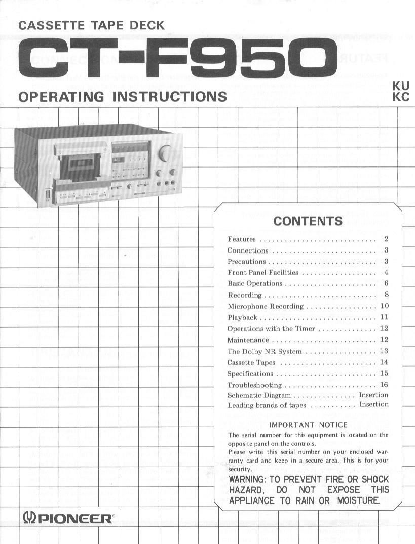
Pioneer ctf 950 owners manual

This is the 16 pages manual for pioneer ctf 950 owners manual.
Read or download the pdf for free. If you want to contribute, please mail your pdfs to info@audioservicemanuals.com.

Page: 1 / 16
left right
pioneer ctf 950 owners manual

Extracted text from pioneer ctf 950 owners manual (Ocr-read)


Page 1

CASSETTE TAPE DECK

T-F95 m

OPERATING INSTRUCTIONS KC

l l

l w
CONTENTS
Features ............................ 2
7T 7 Connections ......................... 3 -
Precautions .......................... 3
7 7 7 7 Front Panel Facilities .................. 4 -
7 Basic Operations ...................... 6 _
Recording ........................... 8
w# Microphone Recording ................. 10 -
Playback ............................ 1 1
Operations with the 'Iimer .............. 12 -
Maintenance ......................... 12
77 The Dolby NR Syslem ................. 13 i
_ __7 A Cassette Tapes ....................... 14 _ 7
Specifications ........................ 15
l 7 w Troubleshooting ...................... 16 of,
Schematic Diagram ............... Insertion
__ A, , + I Leading brands of tapes ........... Insertion ._
W. , IMPORTANT NOTICE -

The serial number for this equipment is located on the
opposite panel on the controls.

Please write this serial number on your enclosed war-
ramy card and keep in a secure area. This is for your
I 7 '7 security.

l

WARNING: TO PREVENT FIRE 0R SHOCK
I HAZARD, DO NOT EXPOSE THIS

I , APPLIANCE TO RAIN 0R MOISTURE.

,#_.

miglomeen T l

Page 2

FEATURES

Transport Section Engineered for Stable Tape Run

This deck I't-atutes the closed loop dual C.ifl\l.llt system Wlllltltv
a capstan is stationed on either side oi the hcacs, This system
maintains a stable contact zit-tween the heads and the tape so lfldl
the tape travels at a constant tension all the time, and it a so helps
to suppress dropouts in the tape and fluctuations in the. level,
Another important pomt is that external vibration transmitted trom
the reel hoses and tape guides to the tape is kept down to the
minimum tor a marked reduction in the modulation noise and both
retording and playback which are iaithlul to the orrginal sound.

The DC servo motor which provides a stable rotational speed is
combined with the ultra-precision-engineered capstan: and good
dynamic balance flywheels to yield a truly superior tape transport
perlormance, and a great improvement in the wow and flutter
characteristics

Yet another prime feature is the mechanical governor motor
with its powerful rotation torque and less ripple. This is used for
tile take-up operations, and enables reliable fast forward and
rewind operations

Three~Head System with Recording/Playback
Combination Head

This deck features a combination head which ts art amalgama
tion at a playback head and a Iccurdlrtx head displaying outstanding
phase characteristics, frequency response, slgnal-to-noisc ratio and
a host of other superior characteristics in a slnglc packaged case, In
addition to the superb high-irequcncy response and wear-resistance,
Pioneer's newly developed lerrilc is used tor the head and this
overcomes the traditional weak point of ordinary ferrite which loll
something to he desired in their handling at high input signals, the
result is a head which not only draw's out the bcst In the perlornr
anct: ul chrome tapes and Icrrlclrrome tapes but also copcsaclrnlra-
bly with metal tapes which ekcel itt dealing with high input signals.
All this translates into birth-quality recording and playback, Another
hirt attraction is that the combination head allows the rccording to
be monitored virtually In real timc when the monitor switch ls
sclcclcd.

Built-In Microprocessor Gives Digital Level
Indication and Tape Counter

lhts deck contains a braln': a 4-bit parallel processing l-Lhip
microproressor which is the secret lllliltlll the digital indication ol
the recording and playback levels on the fluorescent display tubes.
lhc level meter CllJIdS to cover a range imm -20IiB up to HtlB.
Indication belwccn -4dE and Hills is in ldH steps which allows
high-level signals movements in he utasptd at a glantr: and the
recording level to he sat just as easily.

The Ict-el meter can serve to display normal VU readout, o: it
can be made to function as a peak meter to detect accurately
pulse-like sound. Moreover. while the mctcr is working as a peak
meter, the maximum level of the program source can hr: held on the
display simply by depressing the peak hold switch. All these
functions are madt' possible by that» meter switches. ll they are
selected in rlCLl)'ddllCl with the program source \vhrth rs being
recorded, you will bi: assured oi laithiul retorclinxs which leaturca
good signalto-uolse ratio even with program sources with with:
dynamrt ranges

The tape counter rs another dramatic new feature Instead oi the
usual mechanically rotatitut iigurcs. it comesrn the inrrn of a .I-rligtt
'dirtrtron' display tube which makes use of the Illltll'lll micro
protessot and its counter ittnctlon to detect the pulses generated as
the reel bases rotate. These pulses are translated into digits which
are then displayed. this electronic tape counter is extremely handy.

3 *Manulactured under license trom Dolby Laboratories.
*Dolby and D0 are trademarks of Dolby Laboratories.

Equalizer Circuit and Bias Control Mechanism
Aimed at Making the Most of the Tapes'
Characteristics

The most is made of not only metal tapes but also chrome tapes,
I'errlchrome tapes and standard tapes with the tape selector which
selects the equalizer and bias corresponding to the type ol Lapc
used. and also with tin: bias control which allows the bias of the
tape to be ilncly adiustedt Adjustments can thereiora be made to
suit the characteristics of each type of tape. lhe bias control can
also he used to produce the lrequeircy response of your preference.

Feather-Touch Electronic Mechanical Control
Based on LS| (Large-Scale Integrated Circuitry)

the tape transport selector mechanism employs eIt-tt:onu.
mechanical control based on a dual-in-line 24-pin C MOS LS| cirtuit.
You tan set the deck to any mode, whether playback, recordinu,
last forward, rt-wind or stop, .rom om- motle directly with .r leather
touch operation When the tape transport is changed over lrom last
Iorward to play or from last iorward to rewind hy liII' commands
from the Lils program, the deck is put through the stop mode
automatically. this means t'rat the tape is never harmed in any way.
Fven when two mode huttons .trt- t|c|llt'ssttl accidentally together,
the deck rs set to the stop made first and so there is absolutely no
tear of a breakdown ol mallunction,

Microprocessor with Six Different Programs in
Its Memory

The LS| accommodates sis (hilt-rent Pltlfll'tlmki the MEMORV
STOP whith automatically rewinds the tape to the positron where
the tape counter was set to Utlt); the MFVIORV lLAV which
commences playback axarn alter the. tape has been stopped; the
RFPFAT END which repeats tape playbatlt automatically ront the
tape start point; the LOUNTLR RL'PFAT which repeats the tape
playback (tom the start at the profit-1m when- Ihe Iapt comm: was
set during playbatk to 1100' up to the end of the tape 't-wtnd
well as the unattended recording and wakcaip playback luncttons
which can be employed when you hook up an optional timer to the
deck.

VARIETY OF ACCESSORY MECHANISMS

Dolby* Noise Reduction System:

A newly developed low-distortion IC is used lot the Dolby VR
systems 'I his serves to reduce greatly the irritating noise heard when
you play back a tape, and It does this without impairing the sound
uuality ol the original program source. This helps to increase the
dynamic range, and it allows recordings and playback with a gnarl
filgflrII-IOIIOlM: ratio.

Input Selector Switch:

lhls switch can be selected between the program source con-
nected to the rear panel input lacks and the suund trout a micro»
phone.

Output Level Controls with a Click-slop Position
for Easy Pinpointing of the Regular Playback Level:

The output (playback leyoll controls can be used to vary the
output level continuously and they are also coupled to the level
motor. This means that it is possible to check the output level on tilt:
rnclcr, regardless of the strength oi the recording level. When the
controls are set to their click-stop position, the regular playback
level cart also be checked