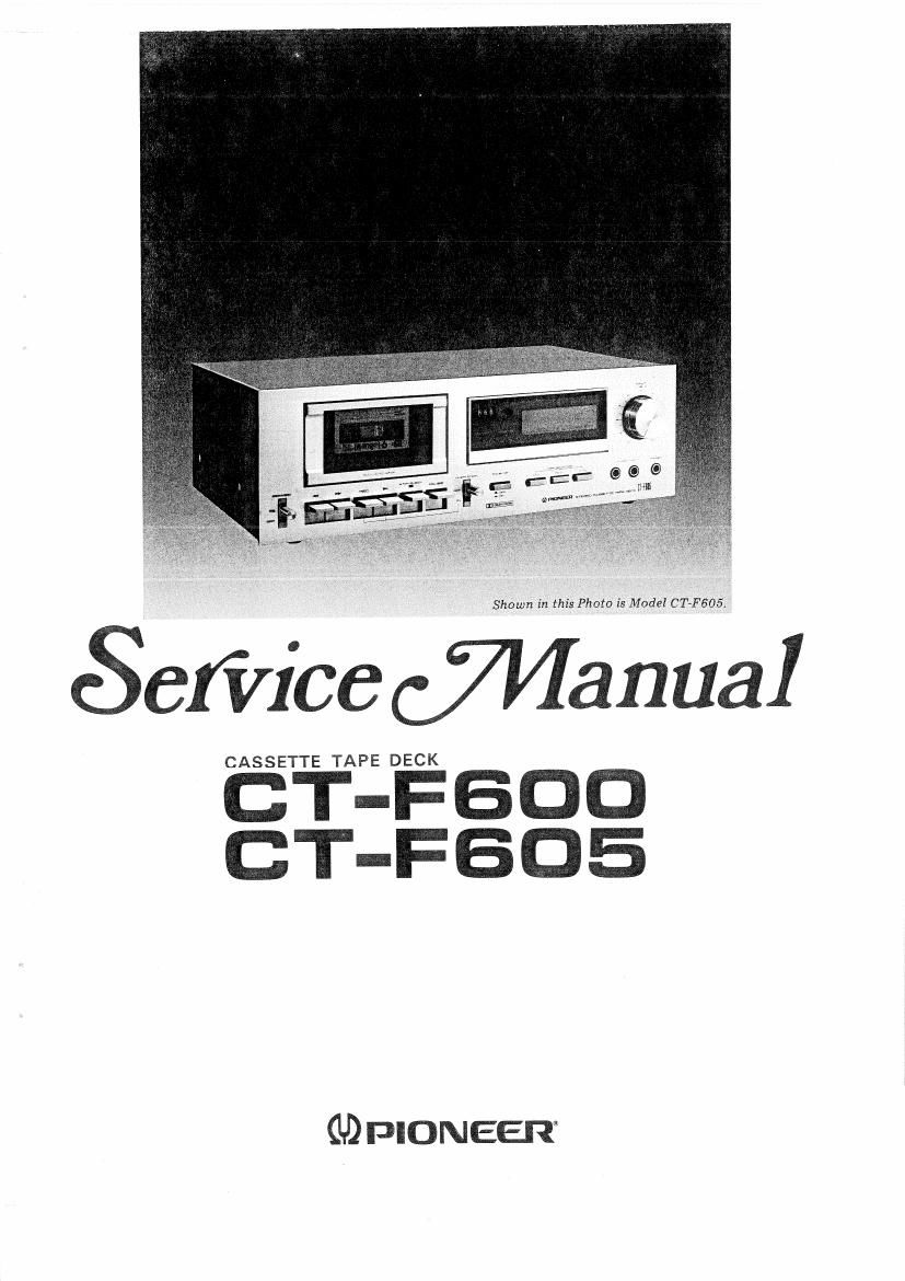
Pioneer ctf 605 service manual

This is the 36 pages manual for pioneer ctf 605 service manual.
Read or download the pdf for free. If you want to contribute, please mail your pdfs to info@audioservicemanuals.com.

Page: 1 / 36
left right
pioneer ctf 605 service manual

Extracted text from pioneer ctf 605 service manual (Ocr-read)


Page 2

MODEL CT-F600 COMES IN SIX VERSIONS DISTINGUISHED AS FOLLOWS:

TYPE Voltage Remarks
Kc AC 120V only Canada model
HE AC 220V and 240V (Switchable) Europe model
H3 AC 220V and 240V (Switchable) United kingdom model
HP AC 220V and 240V (Switchable) Oceania model
D AC 120V, 220V and 240V (Switchable) General export model
D/G AC 120V, 220V and 240V (Switchable) US. military model

MODE L CT-F605/KU

Type Voltage

Remarks

KU AC 120V only

U.S.A. model

0 This service manual is applicable to the CT-F600/KC, CT-FSOS/KU. For servicing
of the other types, please refer to the additional service manuals.

CONTENTS

1. SPECIFICATIONS .................... 3
2. FRONT PANEL FACILITIES ............. 4
3. DISASSEMBLY ...................... 6
4. PARTS LOCATION ................... 10
5. MECHANICAL DESCRIPTIONS
5.1 Play Operation ................... 12
5.2 Autostop Operation ............... 12
5.3 FF. REW ...................... 13
5.4 Auto-start Operation ............... 13
6. CIRCUIT DESCRIPTION
6.1 Recording/Playback Circuit .......... 14
6.2 Muting Circuit ................... 16
6.3 Oscillator ...................... 16
6.4 Level Meters .................... 16
7. BLOCK DIAGRAM ................... 17
8. LEVEL DIAGRAM .................... 18
9. MECHANICAL ADJUSTMENT
9.1 Tape Speed Adjustment ............. 19
9.2 Pinch Roller Pressure Adjustment ...... 19
9.3 FF (REW) Switch Adjustment ........ 19
9.4 Reel Base Torque Adjustment ......... 20
9.5 Motor Switch Adjustment ........... 20
9.6 Pause Timing Adjustment ............ 20
9.7 Play Timing Adjustment ............ 21
9.8 Leaf Switch Timing Adjustment ....... 21

10. ELECTRICAL ADJUSTMENTS
10.1 Head Azimuth Adjustment ...........
10.2 Playback Equalizer Check ...........
10.3 Playback Level Adjustment ..........
10.4 REC Switch Operation Timing Check . . . .
10.5 Meter Adjustments ................

10.6 Approximate Adjustment of Recording
Current ........................

10.7 Approximate Adjustment of Recording
Bias ..........................

10.8 Recording and Playback Frequency
Response Adjustments ..............

10.9 Recording Level Adjustment ..........

11. SCHEMATIC DIAGRAMS, P.C. BOARD
PATTERNS

11.1 P.C. Boards Connection Diagram .......

11.2 Schematic Diagram ................
12. PARTS LlST ........................
13. EXPLODED VIEWS

13.1 Exterior .......................

13.2 Mechanism -1 ...................

13.3 Mechanism - 2 ...................
14. Packing ............................

24

24

25
25

27
30
32

34
37
40
43