Pioneer ctf 1000 service manual

This is the 11 pages manual for pioneer ctf 1000 service manual.
Read or download the pdf for free. If you want to contribute, please mail your pdfs to info@audioservicemanuals.com.

Page: 1 / 11
left right
pioneer ctf 1000 service manual

Extracted text from pioneer ctf 1000 service manual (Ocr-read)


Page 1

CT-«Ffl Doc:

2. M ECHANICAL ADJUSTMENTS

To PI'ESS the PLA Y lover who. there IS rm was.
some half m Lhe we He Comparlnfswt, [mt
tum ON the , sens hail" dewctur swwuh
(n11Cro~swltclxl, and than mesa the lever whlly
holding down the c ILL, dotevtur pm

Ordinary ZiLlefInLRLS wyll reqmru wnmvul of
mg meuhamcal assembly from (he mam body
but WIthour, di§

PINCH ROLLER COMPRESSION
ADJUSTMENT .
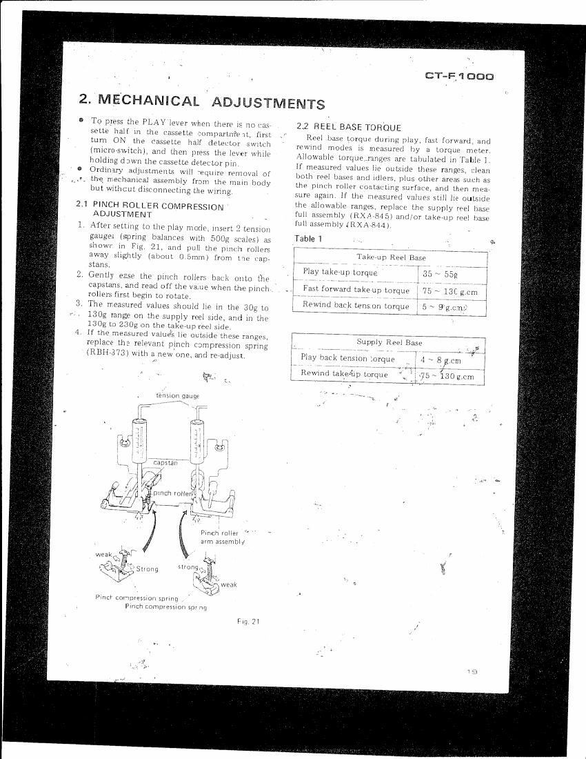
After setmng to the? play m 0dr. 1mm: 2 amazon
gauges (sprmg balanr" wnh 500g scales} 21;
shown m Hg , :r . pull Llw pmch rollb
away sllghtly (almuL ()5mm) from the var
Stuns

valv eusv the pun-h mtlers ball; onto flit
capsLans. and read off £11? value when the meh
rollers first began Lu mime.

Th9 measured values should lie m the 30g L0
130g range on the sup y reel slde, and m Llw
130g 1:) 230g on the Lgkeup (Gel side.

If the) measured value} lie oulside tltme ranges,
replace the relm" pinch compression sprmg
(liBlliWSl wrth a new'one. anC readjust

Pmch mlPr
am asser'lev
yin
C: _
4:4 Stvm'vg

\

weak

P rvch Compvesnwv sprmg
me: Lommosmon 5m mg

Fri; 21

22 REEL BASE TORQUE

Red lmsz yorqufl during: play, {an forward, and
rewmd modes lS mmmuh by a torque mcwh
Allowable Lorque ranges art Lulmlamd m 'lalr
lf measured vuluvs lm outsldo LhOM rrmgos.
both reel buses and :dlorg plus other new; :uch as
the pmvh roller contamng surfack, and Lhen mmr
sure ugam If the measured valuF. auli he ouledr
the alluwahlu rangea replace the supply reel base
full umbiy in 45) and/or Lake-up rm)! haw
l'Lzllr__Jn1l)ly JHXAVRMJ

Table 1

r, ,,,,,,,,, ,, MAW

* *nrup RNA] B: t,
r , r " '7
Play Lakerup mrqua
Fast forward takerup torque l 7'

Romml back tensum Lurque

li Supply Reel Rice

Page 2

2.3 TAPE SPEED
1. Connect a frequency Counter to the line out«
put terminals. «
. Set the PITCH CONTROL to the center UllCli
strip. V
. Playback the Skill section of the S'IDVSOl test
tape used for checkingtape speed and wow and
flutter. The frequency at the beginning of the
tape should be within 2995 to BOUND lfit is
not adjust by means of the semrfixed volume
in the motor control assembly (as shown in
Fig. 22). f
2.4 FAST FORWARD AND REWIND MODE
INVERSION
When SWitChing hack rind forth between fast

forward and rewind modes. the rotating direction
of the fast forward motor Is reversed, and the fast

forward idler is inverted, The force applied in this'

latter operation may be adjusted by regulating the
fast forward lever-springr as shown in Fig. 23 To
increase the force applied. shift the spring across
to the left (direction. fiflthe arrow) 1
When making this adjustment, place the assemb?
ly in ri horizéntal position. or tilt the front upr
wards at an angle of 453. Shift the fast forward
lever spring across (it necessary} so that the fast
forward idler will invert smoothly
0 After completing this adjustment, retheck the
fast forward/rewmd iiiode irversion operation
several times to ensure that there are no ah»
normal vibrations etc. , ' ,_
1f none of the fast forward lever spring posr
tions is sufficient for norms. inversion upern
tion. replace the fast forward lever spring
(RBHVJSGE) and fast forward idler full assembly
(RXA-SB] ).

2.5 WOW AND FLUTTER
Rotational dexiations in the tape transport sys-
tem of the CTF] 000 high quality cassette deck,
have been suppressed to less than 0 059? (WRMS).
lf riny deterioration in this Spemfled rating is
found, Check the followrng points, and 0 Pan,
adjust. or replace as necessary.
. Lr pstan curvattire, vibration, soiling.
. Wobble iri flywheel thrust.
. Deterioration or soiling of capstan belts
. Pim'h roller soiling or compression ahntimial~
ity.
Takerup :dler soiling. eccentrimty, or rom-
pression abnormality.
. Torque deviations in take-tip reel base.
.\l:normal back-tension values.
. Torque deviation due to irregular operatIO'i of
sensing swruh or tape counter.
. Faulty cassette tapes bweiii sod.

2.6 REPLACEMENT OF MICROSWITCHES

There are 3 sets of microswitches operated
(turned (DNyOFF) when a Cassette half is loaded in
the cassette, compartment These include (i) erase
prevention switch. (ii) chrome nape detector
switcli,_ and (iii) cassette half detector switch If
any» of these switches are replaced, check that all
new switches function properly when a cassette
lléllf is loaded.

capstan motor

i
motor control assembly
Fig 22