Pioneer ct 91 a owners manual

This is the 16 pages manual for pioneer ct 91 a owners manual.
Read or download the pdf for free. If you want to contribute, please mail your pdfs to info@audioservicemanuals.com.

Page: 1 / 16
left right
pioneer ct 91 a owners manual

Extracted text from pioneer ct 91 a owners manual (Ocr-read)


Page 1

Opera ting

Instructions

The side wood panel of model CT-91a has a
walnut grain PVC finish.

Thank you for buying this Pioneer product.

Please read through these operating instructions so you will know
how to operate your unit properly. After you have finished reading
the instructions. keep the manual in a safe place for Iuture
reierenoe.

In some countries or regions. the shape of the power plug and
power outlet may sometimes differ from that shown in the
drawings. However. the method of connecting and operating the
unit is the same.

WARNING : TO PREVENT FIRE OR SHOCK
HAZARD, DO NOT EXPOSE THIS APPLIANCE TO
RAIN OR MOISTURE.

IMPORTANT NOTICE
[FOR U.S. and Canadian models]

The serial number for this equipment is located on the rear panel.
Please write this serial number on your enclosed warranty card
and keep it in a safe place. This is for your security.

[For Canadian model]

CAUTION : TO PREVENT ELECTRIC SHOCK DO
NOT USE THIS (POLARIZED) PLUG WITH AN
EXTENSION CORD, RECEPTACLE OR OTHER
OUTLET UNLESS THE BLADES CAN BE FULLY
INSERTED'TO PREVENT BLADE EXPOSURE.

ATTENTION : POUR PREVENIR LES CHOCS
ELECTRIOUES NE PAS UTILISER CE1TE FICHE
POLARISEE AVEC UN PROLONGATEUR UNE
PRISE DE COURANT OU UNE AUTRE SORTIE DE
COURANT, SAUF SI LES LAMES PEUVENT ETRE
INSEREES A FOND SANS EN LAISSER AUCUNE
PARTIE A DECOUVERT.

FEATURES .............................................. 2
PRECAUTIONS ON INSTALLATION ------ --- .

coNNEcrIONs .........................
FRONT PANEL FACILITIES - - ~-
COUNTER MODES -------
PLAYBACK ............
MUSIC SEARCH (MS) ~ ... ... .
RECORDING ............................................

tooowonacom

STEREO CASSETTE DECK

C T-91a so

eI

CONTENTS

(or

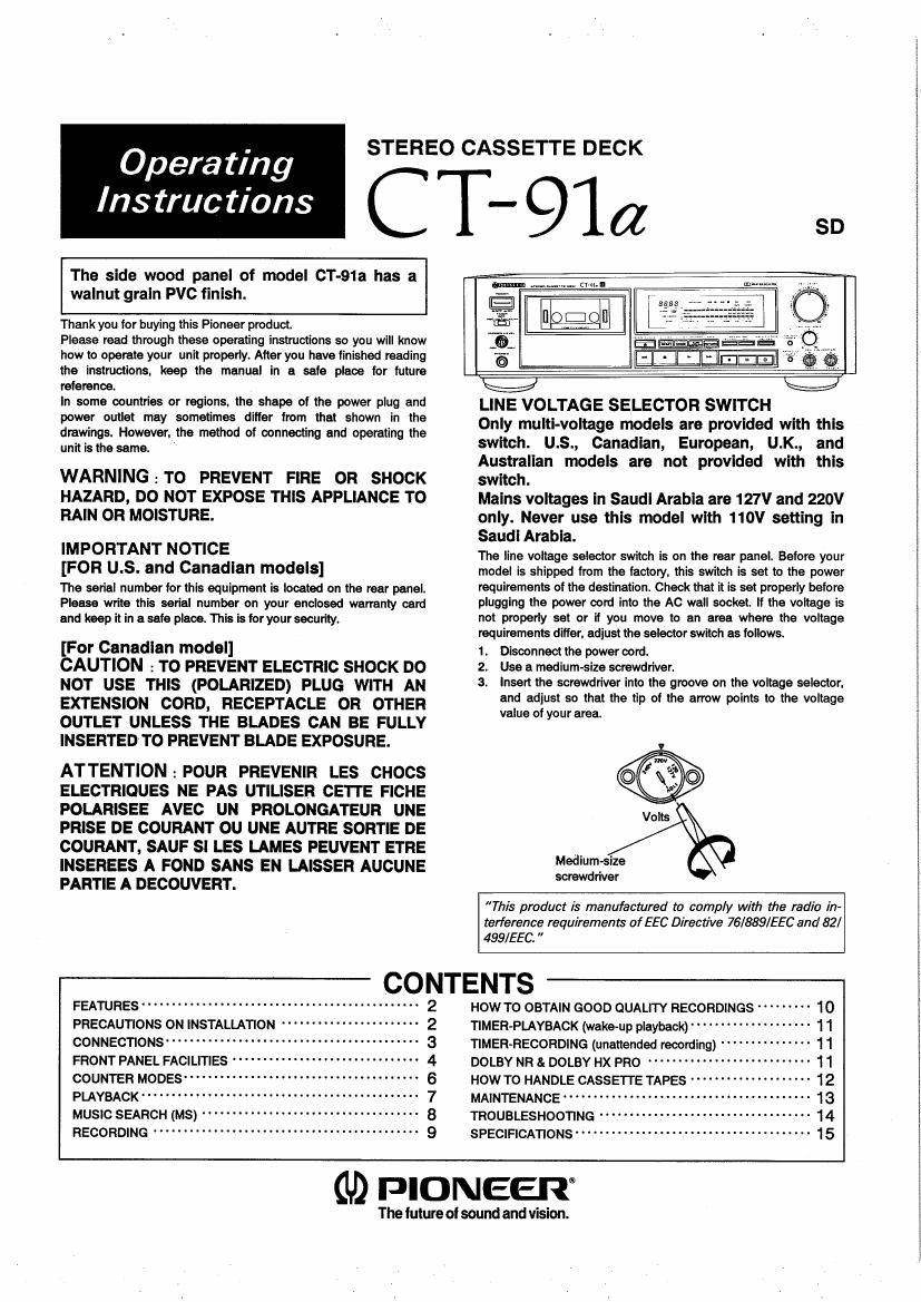
LINE VOLTAGE SELECTOR SWITCH

Only mum-voltage models are provided with this

switch. U.S., Canadian, European, U.K., and

Australian models are not provided with this

switch.

Mains voltages In Saudi Arabia are 127V and 220V

only. Never use this model with 110V setting in

Saudi Arabia.

The line voltage selector switch is on the rear panel. Before your

model is shipped from the factory. this switch is set to the power

requirements of the destination. Check that it is set properly before

plugging the power cord into the AC wall socket. If the voltage is

not properly set or if you move to an area where the voltage

requirements differ. adjust the selector switch as follows.

1. Disconnect the power cord.

2. Use a medium-size screwdriver.

3. insert the screwdriver into the groove on the voltage selector.
and adjust so that the tip of the arrow points to the voltage
value Of your area.

Medium-size
screwdriver

This product is manufactured to comply with the radio in-
terference requirements of EEC Directive 76/889/EEC and 82/
499/EEC.

How To OBTAIN GOOD OUALITY RECORDINGS --------- 10
TlMER-PLAYBACK (wake-up playback) ------------ -- l 1
TIMER-RECORDING (unattended recording) -- 11
DOLBY NR & DOLBY HX PRO ...................... . . 1 1
HOW To HANDLE CASSETTE TAPES --------------- - - 12
MAINTENANCE ........................ . . . . 13
TROUBLESHOOTING - -- - 14
SPECIFICATIONS ....................................... 15

GD PIONEEIT

The Iuture of sound and vision.

Page 2

FEATURES

SHORTER SIGNAL PATHS

Mono-construction allows the circuits for the left and right channels
to be completely independent. resulting in excellent channel
separation The nonrinductive playback circuit eliminates mutual
interference during operation of the microcomputer or mechanism.
The power supply section is separated from the rest of the unit and
the center stay prevents the formation of magnetic fields. Control
operate the corresponding circuits by remote control.

STABILIZED TAPE PATH

Noise resulting from irregular rotation and external vibrations has
been reduced to a minimum. To obtain a stabilized tape tension
and head touch. a dual capstan system has been employed.
consisting of a newly developed cassette stabilizer and pinch
rollers and capstans on both sides of the head. In this way a wow
and flutter of only (102296 WRMS ( i 0.052% DIN) has been
realized.

VIBRATION-FREE AND RESONANCE-FREE
CONCEPTION

From the chassis and the bottom plate to the inside of the
insulators. honeycomb construction based on vibration attenuation
characteristics data is used. This guarantees an especially
high-rigidity. and vibrations are dispersed in different directions.
Thus. vibrations are immediately reduced. preventing deterioration
of the sound quality due to vibration and resonance. resulting in
clear sound. The transformer case is highly rigid and made of cast
iron which possesses excellent vibration attenuation characteristics
MW

RECORDING LEVEL CALIBRATION

When using tapes with poor sensitivity the level of the recorded
sound (playback level) tends to drop. even it the input level of the
program source was adjusted to an optimum value for recording.
To compensate for insufficient tape sensitivity the recording level
can be calibrated to increase the level by the amount it decreases
during playback.

Calibration is especially effective when recording with the Dolby
NR Systems. because the noise reduction effect is optimum when
recording level and playback level are the same.

PRECAUTIONS ON INSTALLATION

HEAT

Do not place the unit neara heating device. on top of the amplifier
or in a location where it is exposed to direct sunlight, as excessive
heat may damage the finish and internal parts. Also. do not place a
cloth on top of the unit or block the provided ventilation openings in
any other way. Always make sure that the installation location
provides sufficient ventilation to prevent overheating.

HUMIDITY, CONTAMINATION

Do not install the unit in an excessively humid or dusty location. as
this may cause malfunctions and breakdowns. Also. avoid placing
the unit next to kitchen counters or other locations where it is
subjected to oily fumes.

NOISE INTERFERENCE

When the unit is placed directly on top of the amplifier it may pick
up humming or other noise during recording. A turned-on TV set in
close vicinity may also cause noise.

DEW CONDENSATION

When the unit is moved from a cold to a warm environment, or
when the room temperature rises drastically. condensation forms
on parts of the tape transport mechanism. causing malfunctions
when the tape deck is operated immediately. To avoid this. allow
the tape deck to acclimate to the new temperature by waiting about
one hour before operating the unit.

INFORMATION TO USER [FOR U.S. MODEL] .

If necessary. the user should consult Ihe dealer or an ex-
perienced radio/television technician Ior additional sug~

This equipment generates and uses radio frequency
energy and if not installed and used properly, that is, rn
strict accordance with the manufacturer's inslmclionsr
may cause interference to radio and television recep-
rion. II has been rvpe tested and found to comply with
the limits for a Class a computing device in accordance
with the specifications in Subpart .l of Part is of FCC
Rules, which are designed lo provide reasonable prorec.
lion against such interference in a residential installs»
tinn. Howevar, there Is no guarantee that Interference
will not occur in a particular insrallarion.

if lhis equipment does cause interference in radio or

television reception, which can be determined by lum-

ing the equipment of! and an. the user is encouraged to

lry to correct lhe inlerterence by one or more ol the

rollowing measures:

- reorient the receiving antenna

- relocate this equipment with respect to the receiver

- move this equipment away from the receiver

- plug this equipmenl inlo a diIIerent outlet sci lhal
equipment and receiver are on different branch cir-
culls.

gestions. The user may Iind the following booklet
prepared by the Federal Communications Commission
helpful:

"How to identify and Resolve Radio-TV Interference
Problems".

This booklet is available horn the us Government Print-
ing crime, Washington, DC, 20402, Stock No,
ammo-003454.

The above InstrucI/ans apply only to wrirs wnmn wr/i
be operated in me Umred Slates.

[For Canadian model]

This digital apparatus does not exceed the Class B limits for radio noise emissions from digital apparatus set out in the Ra-

dio Interference Regulations of the Canadian Department of Communications.

[Pour le modele Canadien]

Linterférence, radioélectrique générée par cet appareil numérique de type B ne dépasse pas les limites énoncées dans le
Réglement sur les perturbations radioélectriques, section appareil numérique, du Ministere des Communications.

2

E