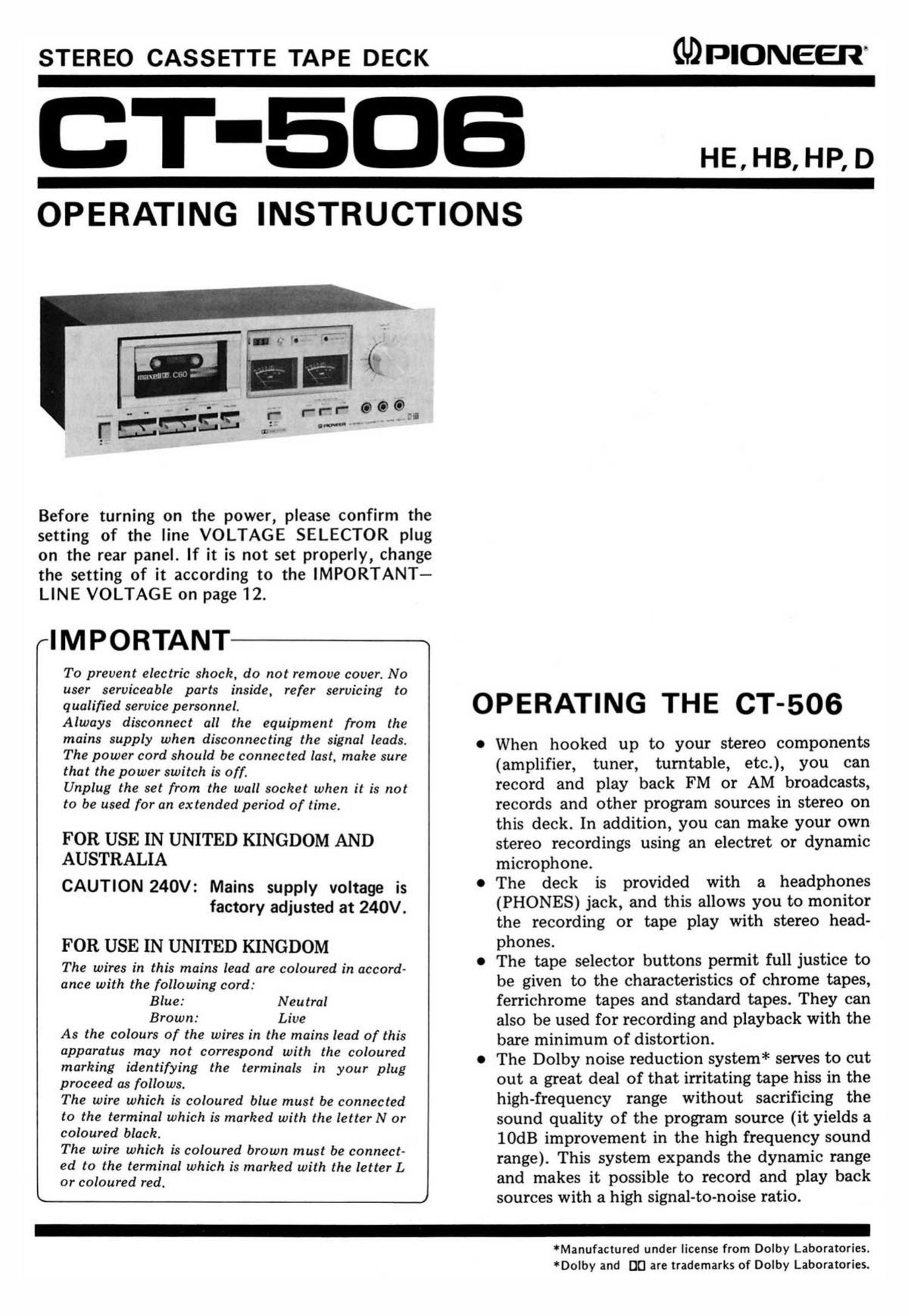
Pioneer ct 506 owners manual

This is the 12 pages manual for pioneer ct 506 owners manual.
Read or download the pdf for free. If you want to contribute, please mail your pdfs to info@audioservicemanuals.com.

Page: 1 / 12
left right
pioneer ct 506 owners manual

Extracted text from pioneer ct 506 owners manual (Ocr-read)


Page 1

STEREO CASSETTE TAPE DECK MPIONEER

T-EDB

OPERATING INSTRUCTIONS

HE, HB, HP, D

Before turning on the power, please confirm the
setting of the line VOLTAGE SELECTOR plug
on the rear panel. If it is not set properly, change
the setting of it according to the IMPORTANT-

LINE VOLTAGE on page 12.

rIMPORTANT

To prevent electric shock, do not remove cover. No
user serviceable parts inside, refer servicing to
qualified service personnel.

Always disconnect all the equipment from the
mains supply when disconnecting the signal leads.

marking identifying the terminals in your plug
proceed as follows.

The wire which is coloured blue must be connected
to the terminal which is marked with the letterN or
coloured black.

The wire which is coloured brown must be connect-
ed to the terminal which is marked with the letter L
or coloured red.

L

OPERATING THE CT-506

The power cord should be connected last, make sure . When. hocked Up to your Stereo components
that the power switch is o. (amplifier, tuner, turntable, etc.), you can
Unplug the set from the wall socket when it is not record and play baCk FM 01' AM broadcast,
to be used for an extended period of time. records and other program sources in stereo on
this deck. In addition, you can make your own
FOR USE IN UNITED KINGDOM AND stereo recordings using an electret or dynamic
AUSTRALIA microphone.
CAUTION 240v: Mains supply voltage is e The deck is provided with a headphdnes
factory adjusted at 240v. (PHONES) jack, and this allows you to monitor
the recording or tape play with stereo head-
FOR USE IN UNITED KINGDOM pheneS- . . .
The wires in this mains lead are coloured in accord- . The tape seleCtor bUttons perm"; full JuStlce to
ance with the following cord: be given to the characteristics of chrome tapes,
Blue: Neutral ferrichrome tapes and standard tapes. They can
Brown: Live also be used for recording and playback with the
As the colours of the wires in the mains lead of this bare minimum of distortion.
apparatus may not correspond with the coloured . The Dolby noise reduction system* serves to cut

out a great deal of that irritating tape hiss in the
high-frequency range without sacrificing the
sound quality of the program source (it yields a
10dB improvement in the high frequency sound
range). This system expands the dynamic range
and makes it possible to record and play back
sources with a high signal-to-noise ratio.

Manufactured under license from Dolby Laboratories.
*Dolby and DC are trademarks of Dolby Laboratories.

Page 2

FRONT PANEL FACILITIES

F'POWER SWITCH

The power comes on when the POWER switch is depressed. The
level meters will then light up. To turn off the power, release the

switch by depressing it again.

[CASSETTE HOLDER

The cassette tape is loaded into this holder. When the STOP/
E]ECT(I) lever is depressed, the holder will iump forward. To
I close it, push the top part of the holder back into position until it
is locked.

"'"RECORD INDICATOR

This light comes on when the play (b) and REC levers are de~
pressed together to indicate that the cassette deck is now set to the
recording mode.

rDOLBY NR INDICATOR

This light comes on when the DOLBY NR switch is set to ON to
indicate that the cassette deck is now set up for recording using
the Dolby NR system or playback using the Dolby NR system.

INPUT LEVEL CONTROLS

Use these controls to adjust the input signal from the MIC iacks

COUNTER RESET BUTTON

Depress this button to reset the tape counter display to "000."

and the rear panel INPUT lacks. Turning them to the right in-
creases the signal level. They are coupled to the left and right
channels when rotated, but you can also use them to adiust the

TAPE COUNTER

This indicates the position of the tape run.


J MIC jACKS

right channel and left channel independently by rotating the
appropriate control and holding the other in position.

L-----


I maven :W_ m
cm PIONEER maneuver oecx CT- 506

LEVEL METERS

These indicate the input level during recording and the output
level during playback.

DOLBY NR SWITCH

These are the input jacks for microphone recording. Plug the left
channel microphone into L and the right channel microphone
into R.

Push this button to ON for recording with the built-in Dolby noise
reduction system and for the playback of tapes which have been
recorded using the Dolby NR system.

NOTE:

Disconnect your microphones from the MIC jack when you are
not using' them. otherwise you will not be able to record to
LINE and DIN input terminals.

TAPE SELECTOR SWITCHES

Depress the switch which corresponds to the type of tape you are
using (refer to Using the tape selector switches" on page 7).

STD: For ordinary tapes, and LH tapes.

Fe-Cr: For ferrichrome tapes

002: For chrome tapes

NOTE:

Be sure to use a chrome tape employing detection holes (see
page 7).

HEADPHONE JACK

This is the output iack for stereo headphones. Plug your head-
phones into this iack when you want to monitor the quality ofa
recording or when you want to listen to a tape privately.

NOTE:
Do not connect a microphone to this Jacks as the microphone

may be damaged.

#

2